
Locate and classify the equipment.
Location trees and configurable hierarchies organise the asset register. Engineers can inspect attributes beside the selected record, identify unassigned equipment and reuse shared views for recurring reviews.
Engineering assets, cable networks and revisions in one workspace.
A desktop engineering application with cloud services for WestConnex New M4 Tunnels in Sydney. Engineers organise equipment by location, inspect cable connections and installation components, compare revisions and prepare reports from the same asset records.
Location trees and configurable hierarchies organise the asset register. Engineers can inspect attributes beside the selected record, identify unassigned equipment and reuse shared views for recurring reviews.
Cable rows connect origin and destination assets with routes and lengths. Containment sections expose trays, supports and conduits, while component settings retain the dimensions and installation factors used in the configuration.
Revision comparisons, source references and change notifications preserve the context of an update. Subscriptions can focus on selected equipment and attributes; review statuses distinguish outstanding changes from actioned and verified entries.
Excel datasheets and registers retain asset identifiers, locations and grouped properties. Containment fill reports trace each value to its area, zone, section and component, so exported figures remain tied to the installation they describe.
From locating equipment to reviewing a change: see the tools engineers use to organise, verify and share infrastructure data.
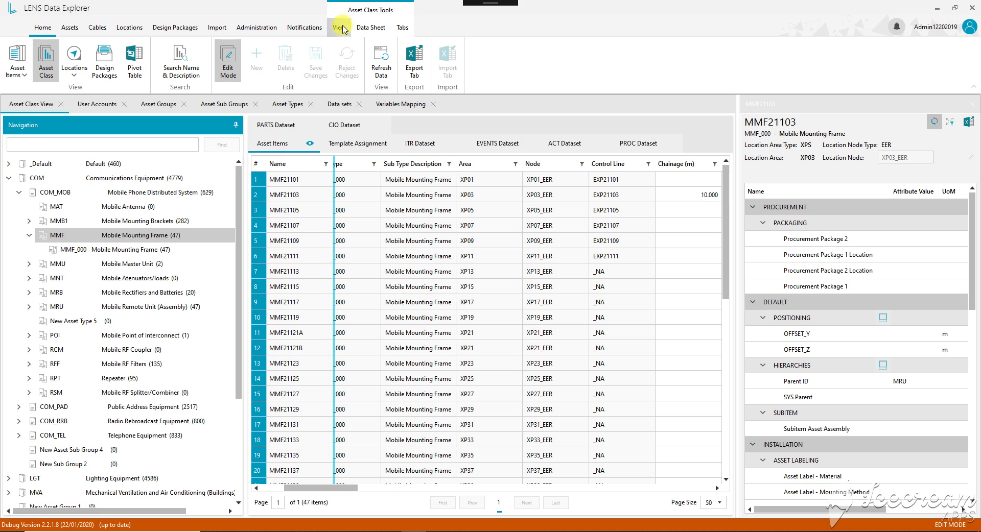
The classification tree narrows the equipment family. Selecting a record keeps its location, positioning and procurement attributes beside the register, so the engineer can inspect the item without losing the surrounding list.
Engineers need to inspect and update an asset without losing its classification and location, then share the relevant record with colleagues.
The register keeps the selected asset beside its table, supports direct property editing and exports either an individual datasheet or a working equipment list to Excel.
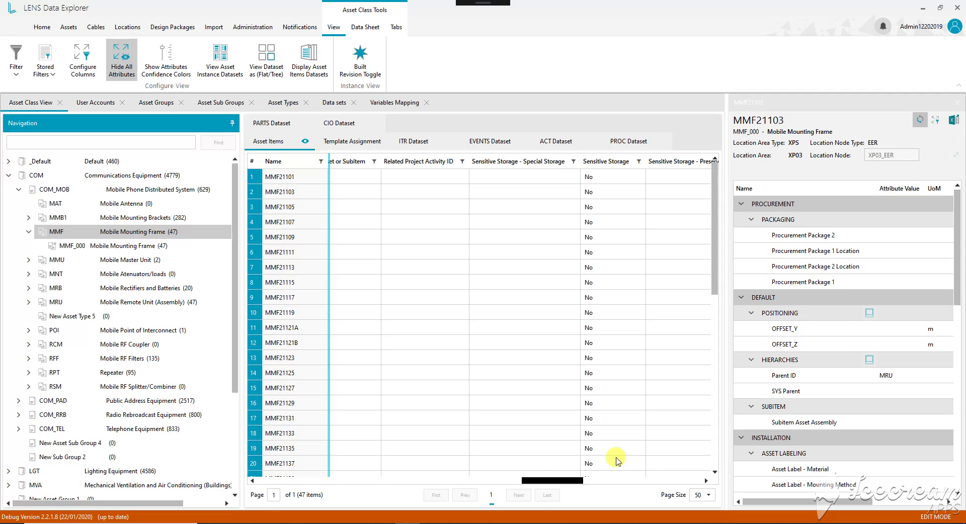
Storage requirements and related project activity can be reviewed across the selected equipment. Dataset tabs and the flat/tree display controls provide different ways to inspect the information attached to an asset.
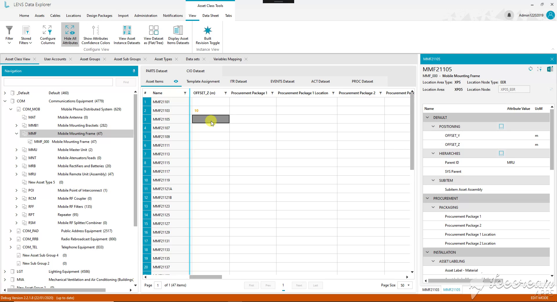
The active cell is a positioning value in metres. The selected equipment record remains open alongside it, allowing the engineer to check the identifier and location while entering the change.
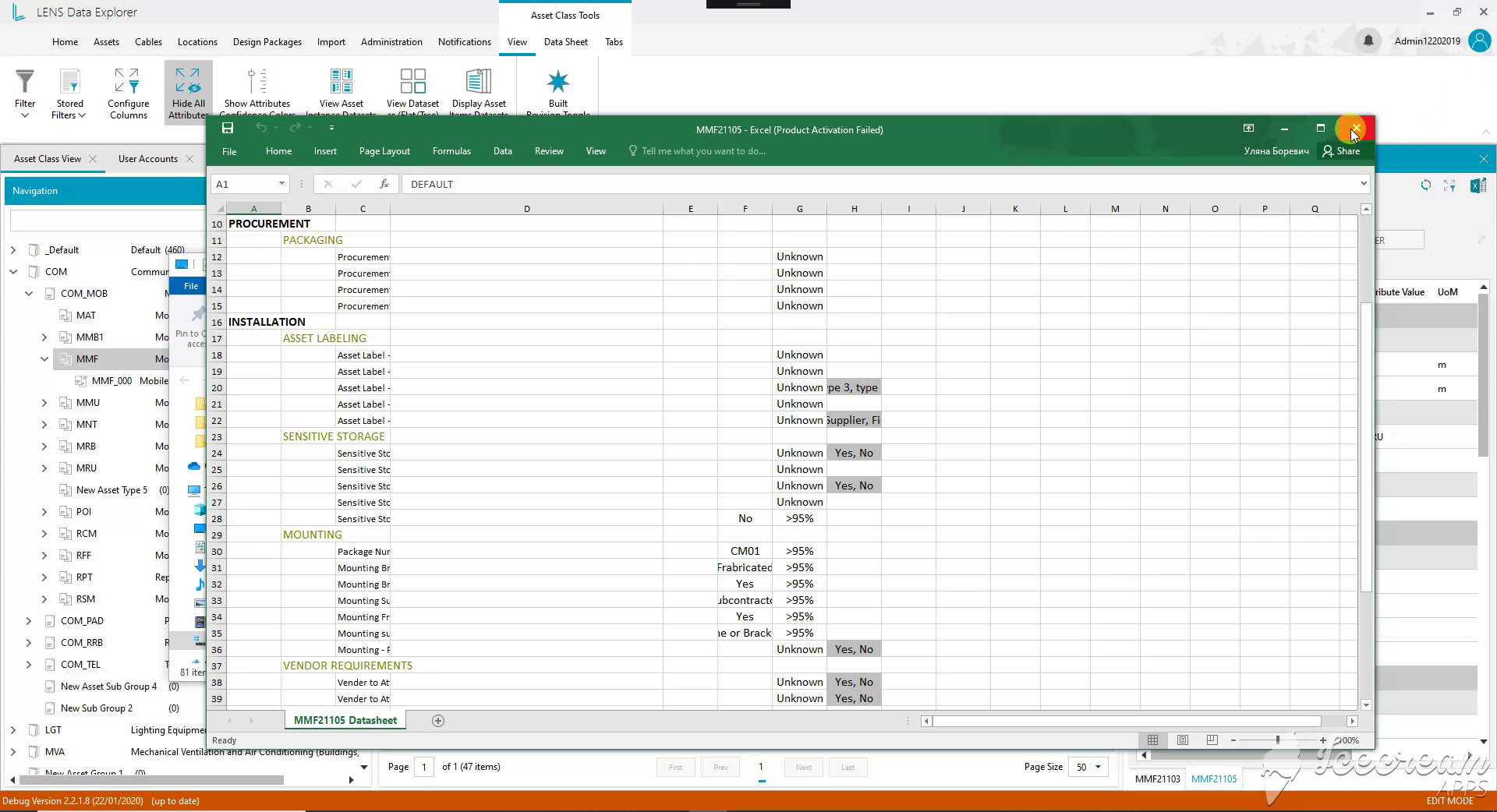
The Excel datasheet retains grouped properties for procurement, installation and mounting. Values and confidence information travel together, giving the recipient more context than a flat list of equipment names.
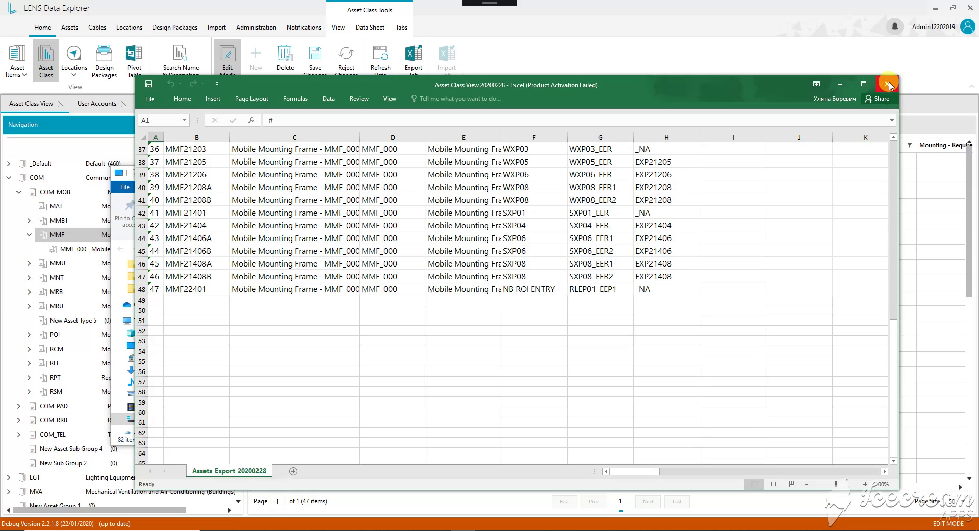
The exported register includes equipment identifiers, descriptions, subtypes and location references. Colleagues can review the selection in Excel and relate each row back to the corresponding LENS record.
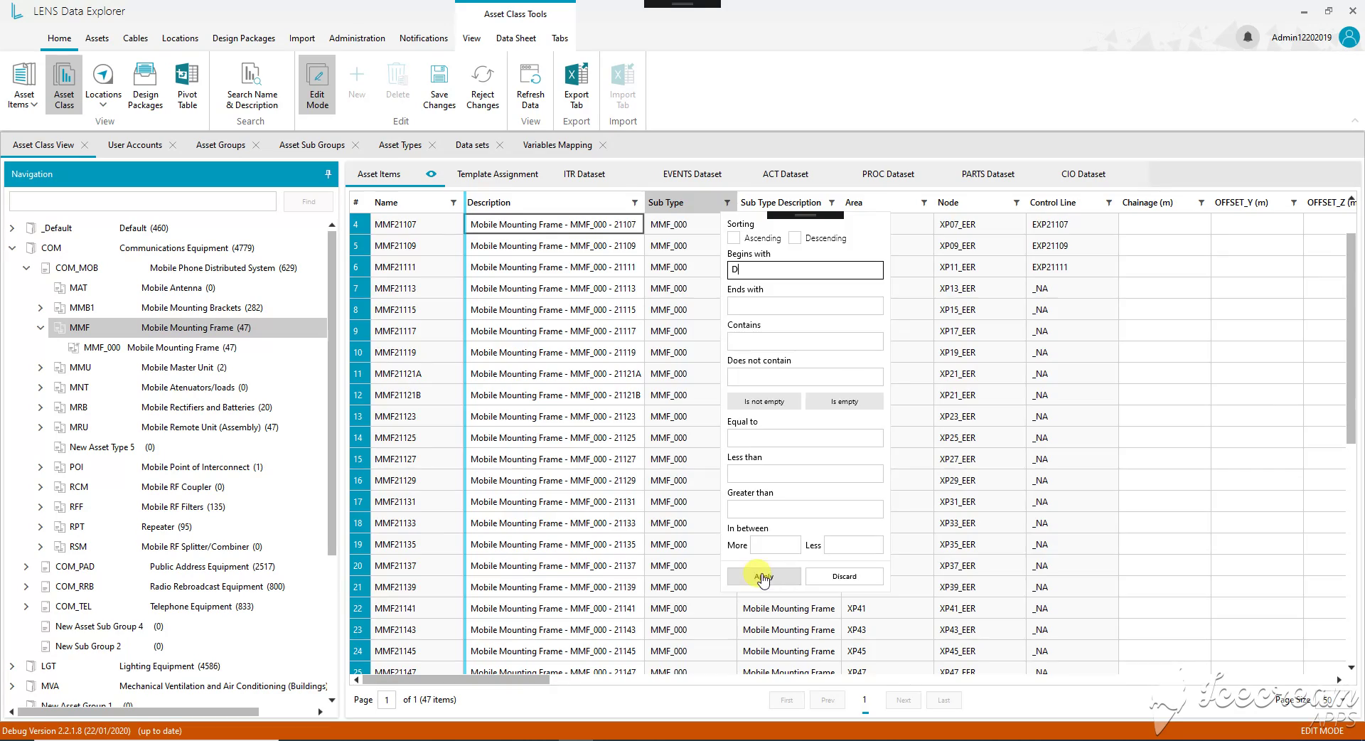
A field filter supports text matching, empty values and numeric comparisons. Engineers can isolate a specific subset or look for missing information before reviewing individual records.
Different engineering reviews need different record selections and columns, including ways to find missing values and reuse a colleague’s configuration.
Field conditions and visible active filters define the selection; the view builder saves engineering attributes, display options and sharing settings with an author and date.
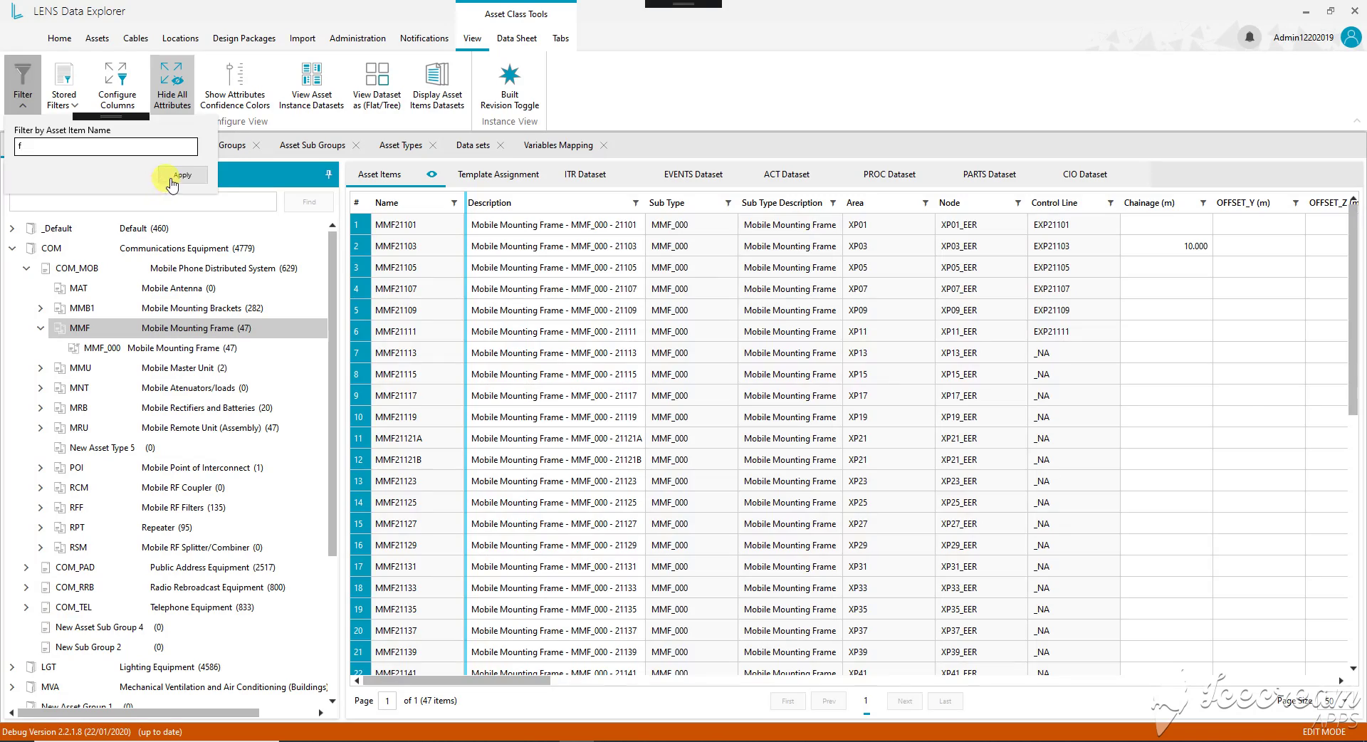
The asset-name filter gives the engineer a direct entry point when an identifier is already known. The register still shows descriptions, subtypes and locations for checking the matching records.
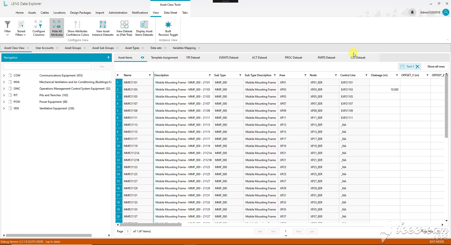
An applied text filter is displayed above the register with controls to remove it or show all rows. This keeps the scope of the current review visible while browsing equipment groups.
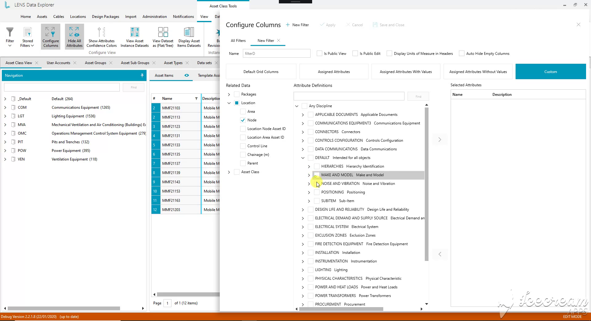
The view builder combines location fields with selected engineering attributes. It also exposes controls for units in headings, hiding empty columns and making the configuration available to other users.
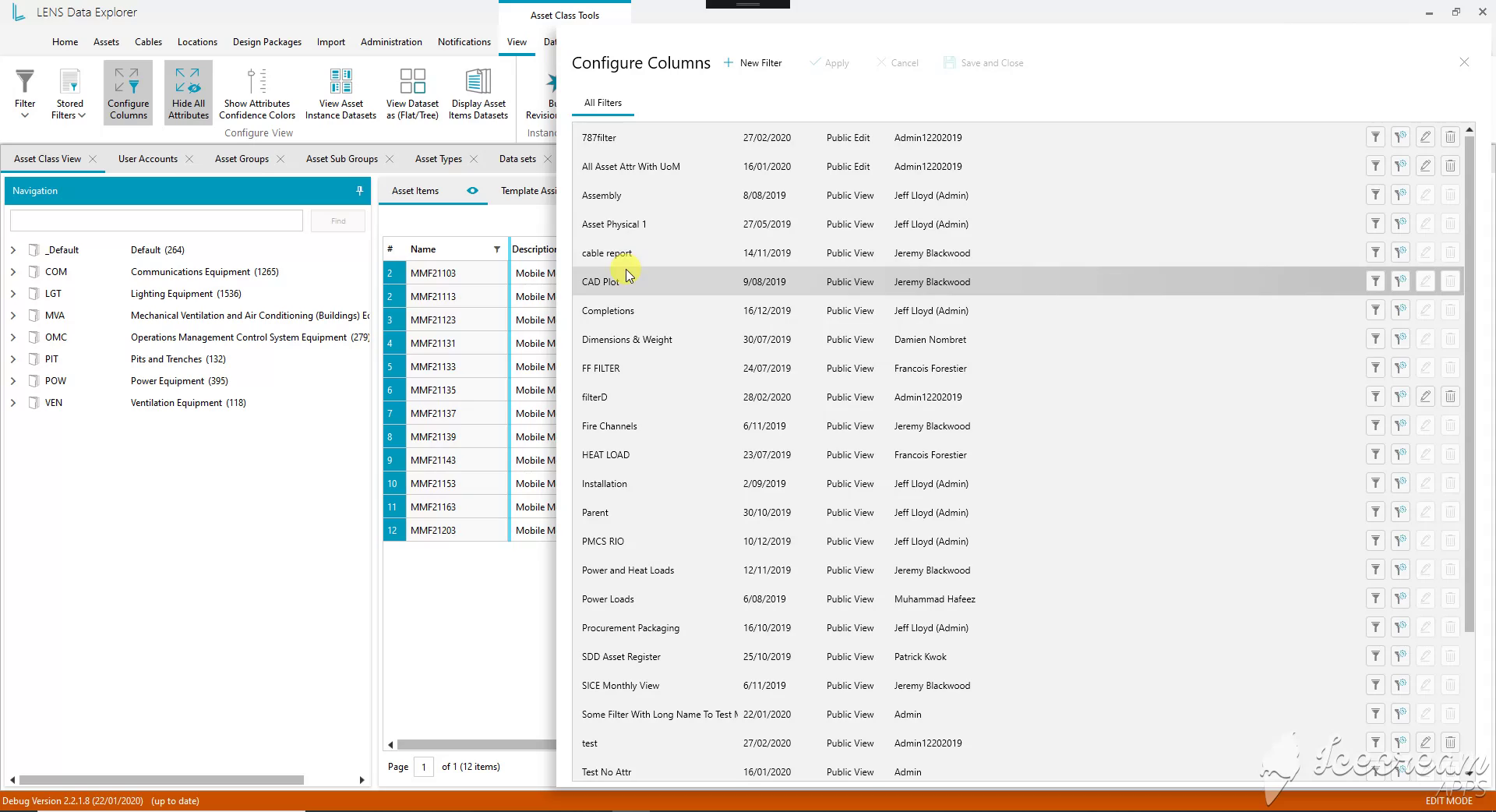
Saved configurations cover tasks such as cable reports, procurement and installation. Each entry shows its author, date and sharing mode, with actions to apply, copy or edit the configuration.
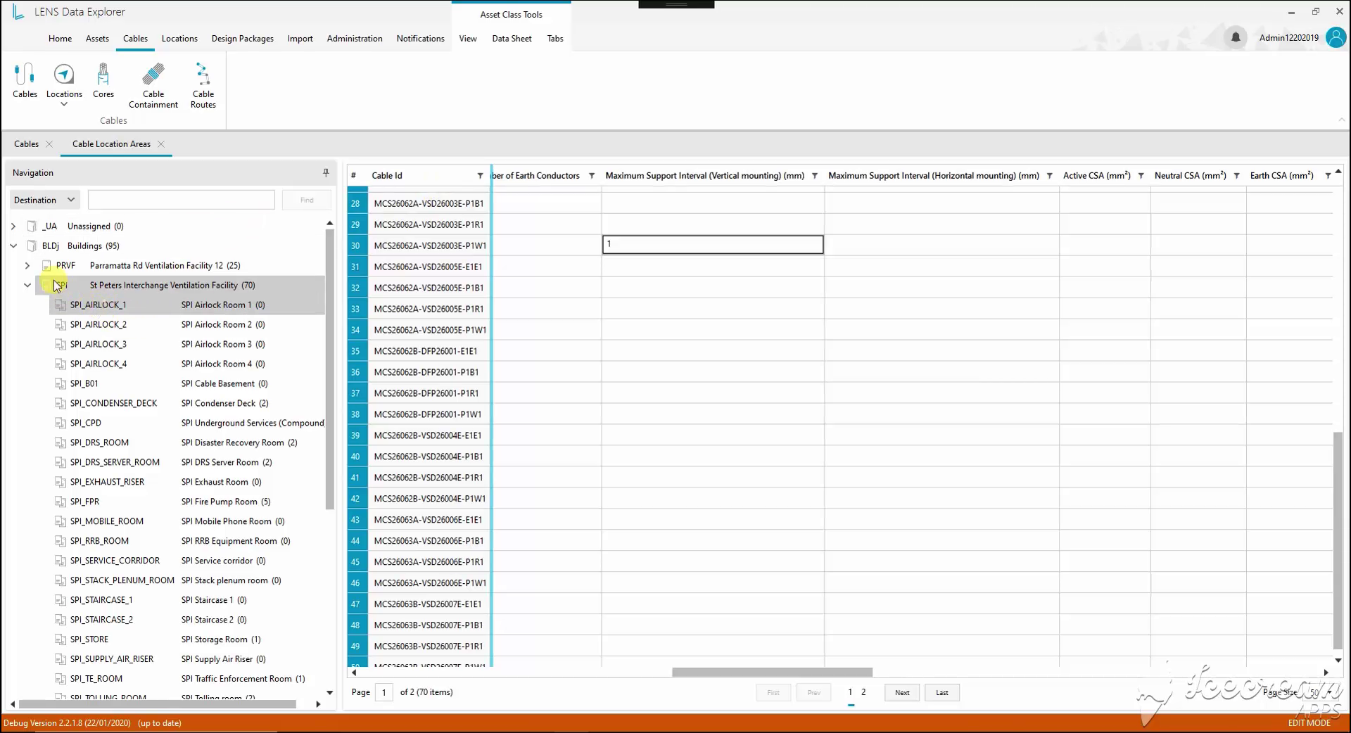
Location navigation groups cables by building and room. The selected register exposes installation properties, including support intervals and conductor cross-sections, alongside each cable identifier.
A cable review needs both connected assets, the route between them and the physical supports that make up the wiring system.
Location-based registers show origin, destination and installation attributes, while expandable component lists and a schematic configurator expose trays, supports and assembly properties.
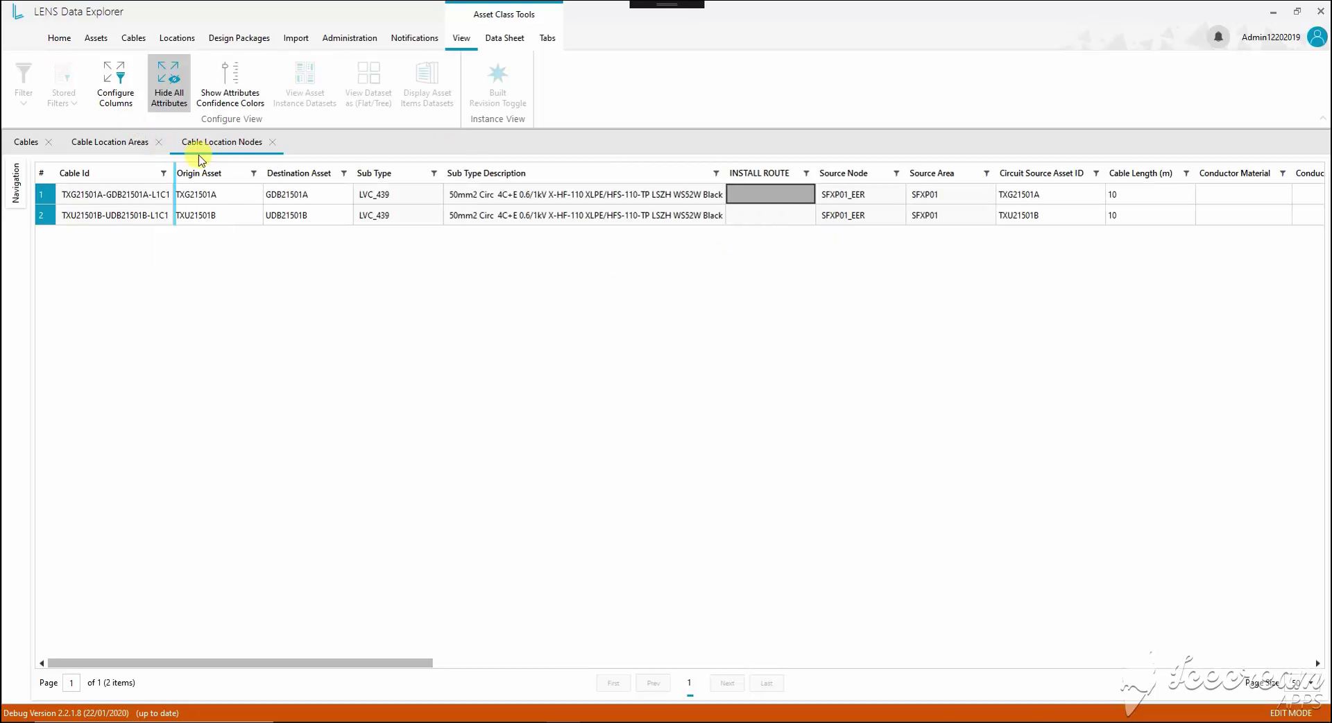
Origin and destination equipment appear in the same cable row. Cable type, source location, installation route and length provide the context needed to review how the two assets are connected.
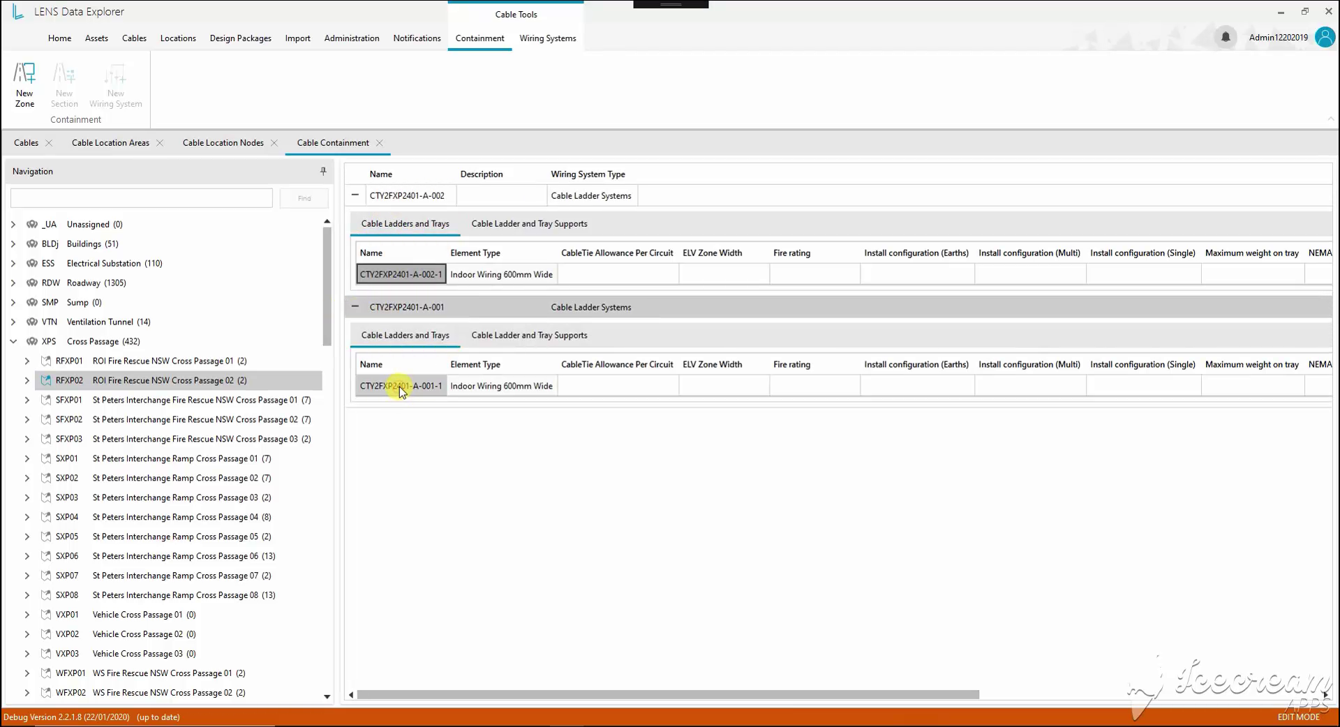
Expanding a wiring system reveals its cable ladders, trays and supports. Their type and installation attributes stay attached to the selected location, so individual components can be reviewed in context.
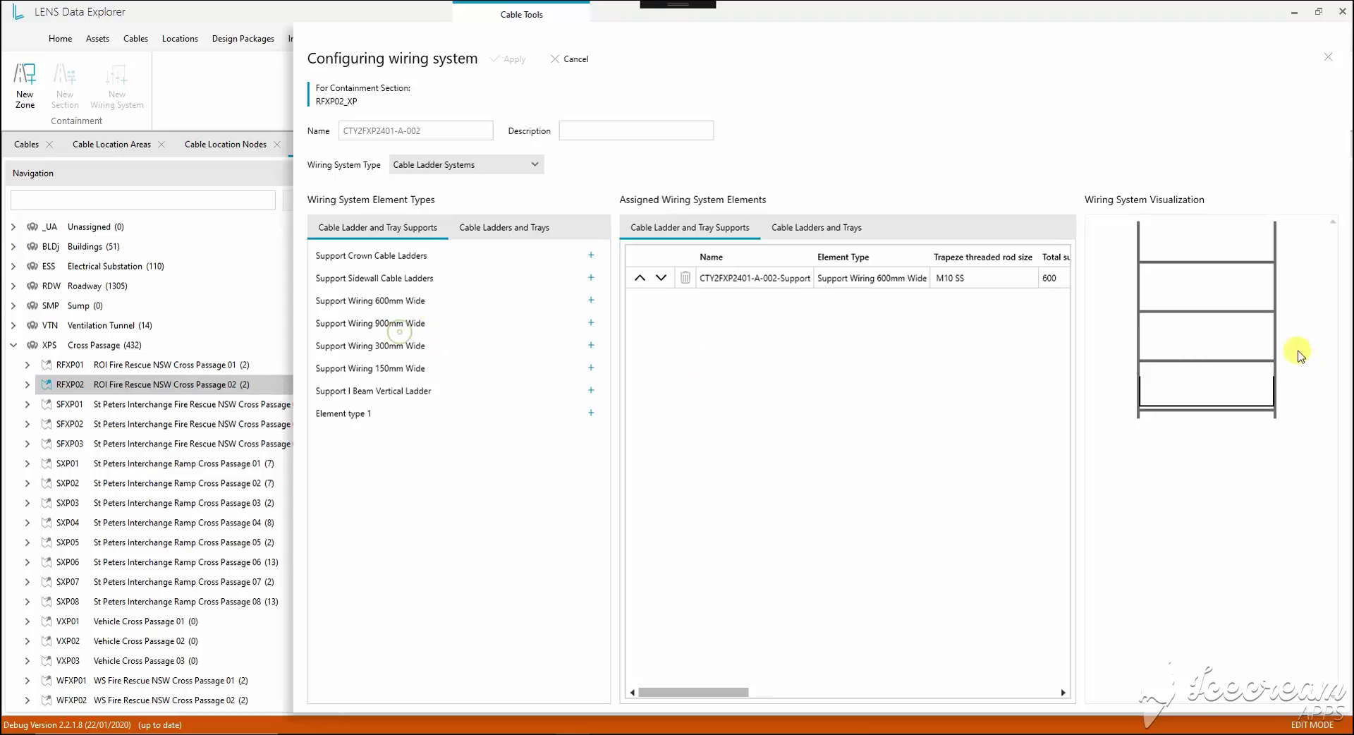
The configurator places available support types beside the assigned elements. A schematic preview accompanies dimensions and fastening properties, connecting the component list with the shape of the assembly.
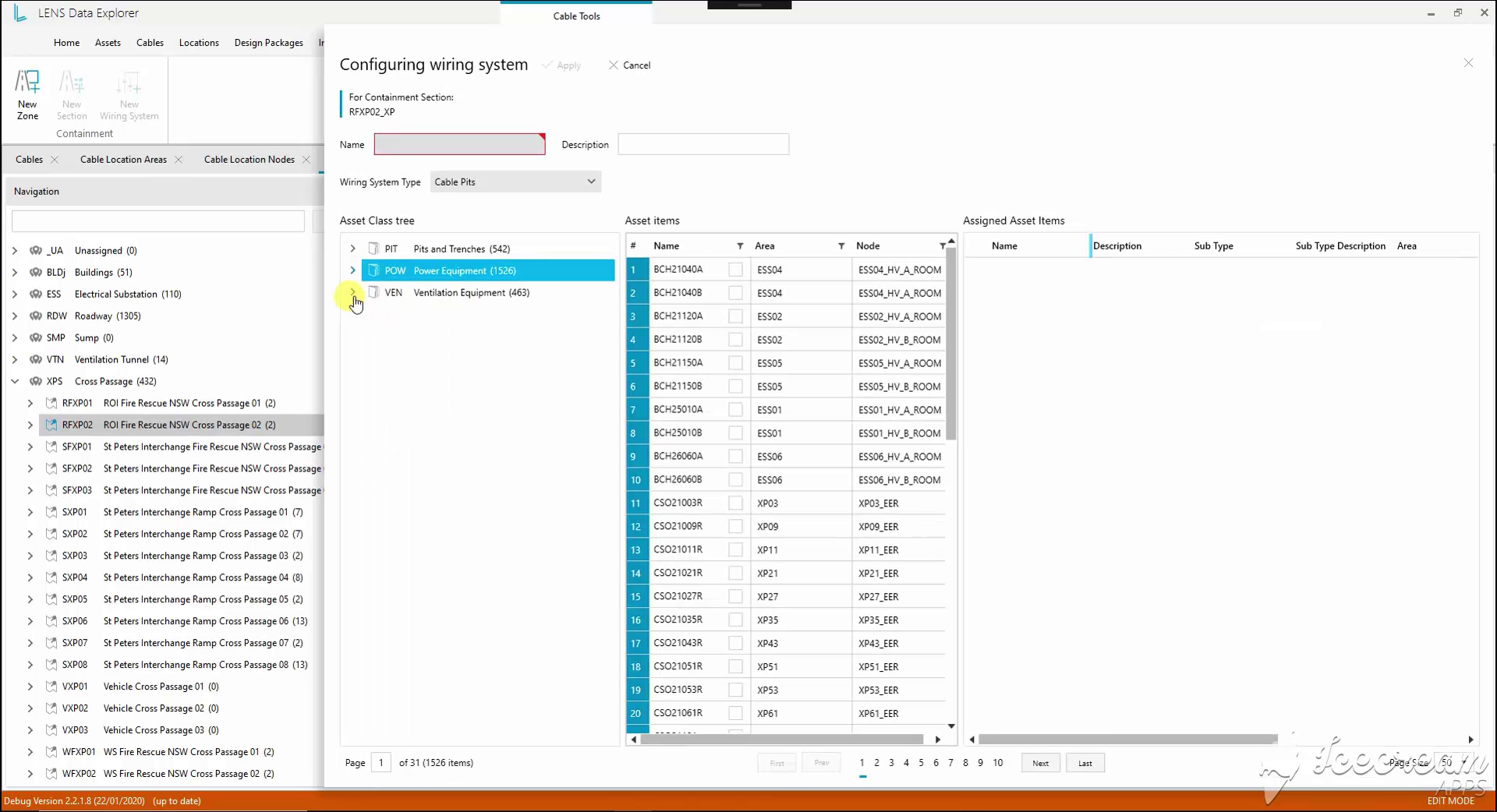
For a Cable Pits system, the selection panel uses the existing asset classification. Engineers can inspect identifiers and locations before assigning a record to the configured containment section.
Assigning an existing asset to a cable system requires checking its identity, handling a replacement explicitly and placing conduit elements within the assembly.
Selection uses the asset classification and location, replacement has a confirm-or-cancel step, and the conduit-bank editor pairs coordinate placement with an assigned component list.
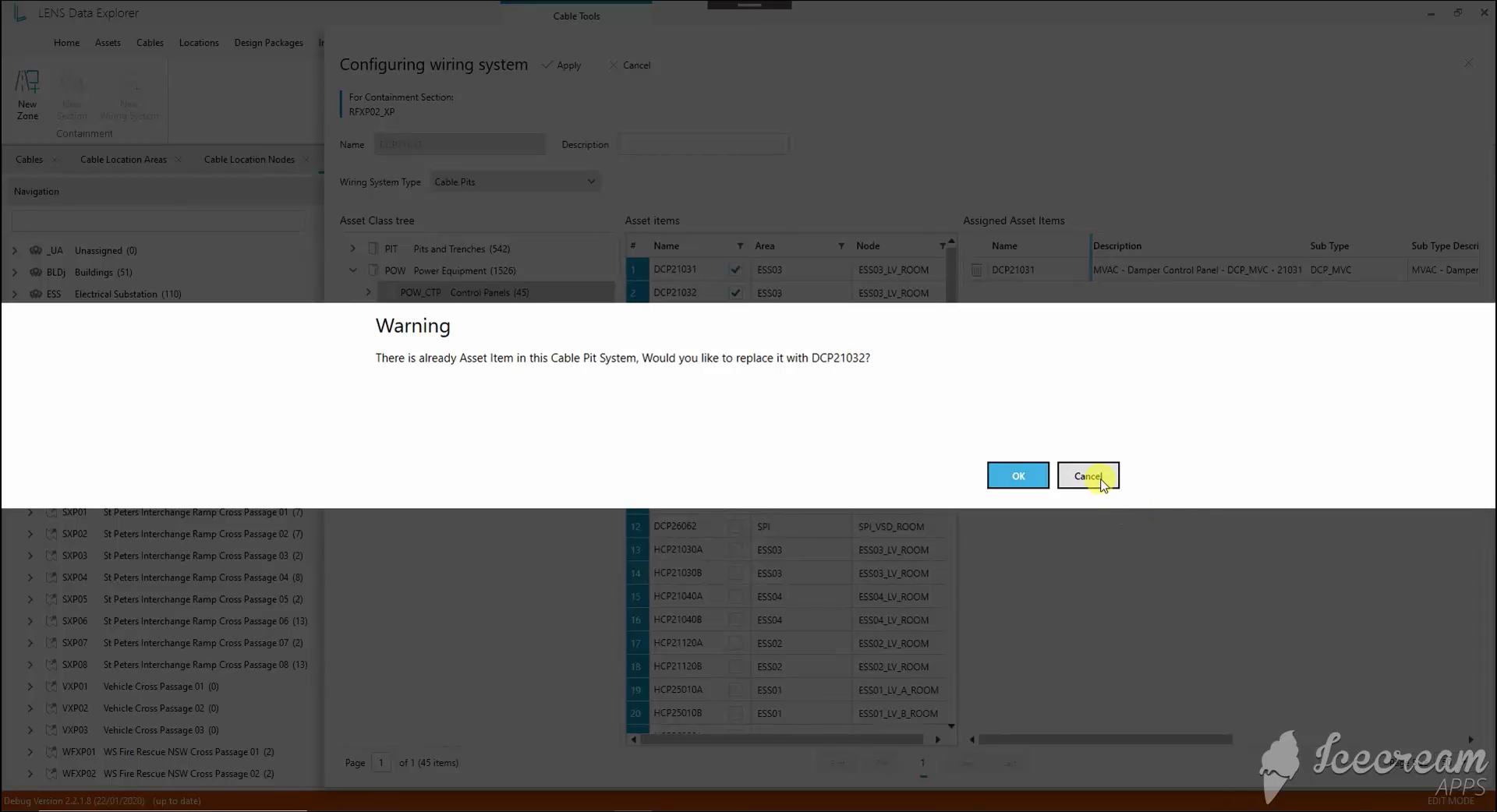
When the Cable Pits system already contains an asset, selecting another opens a replacement warning. The engineer can confirm the new assignment or cancel and keep the current component.
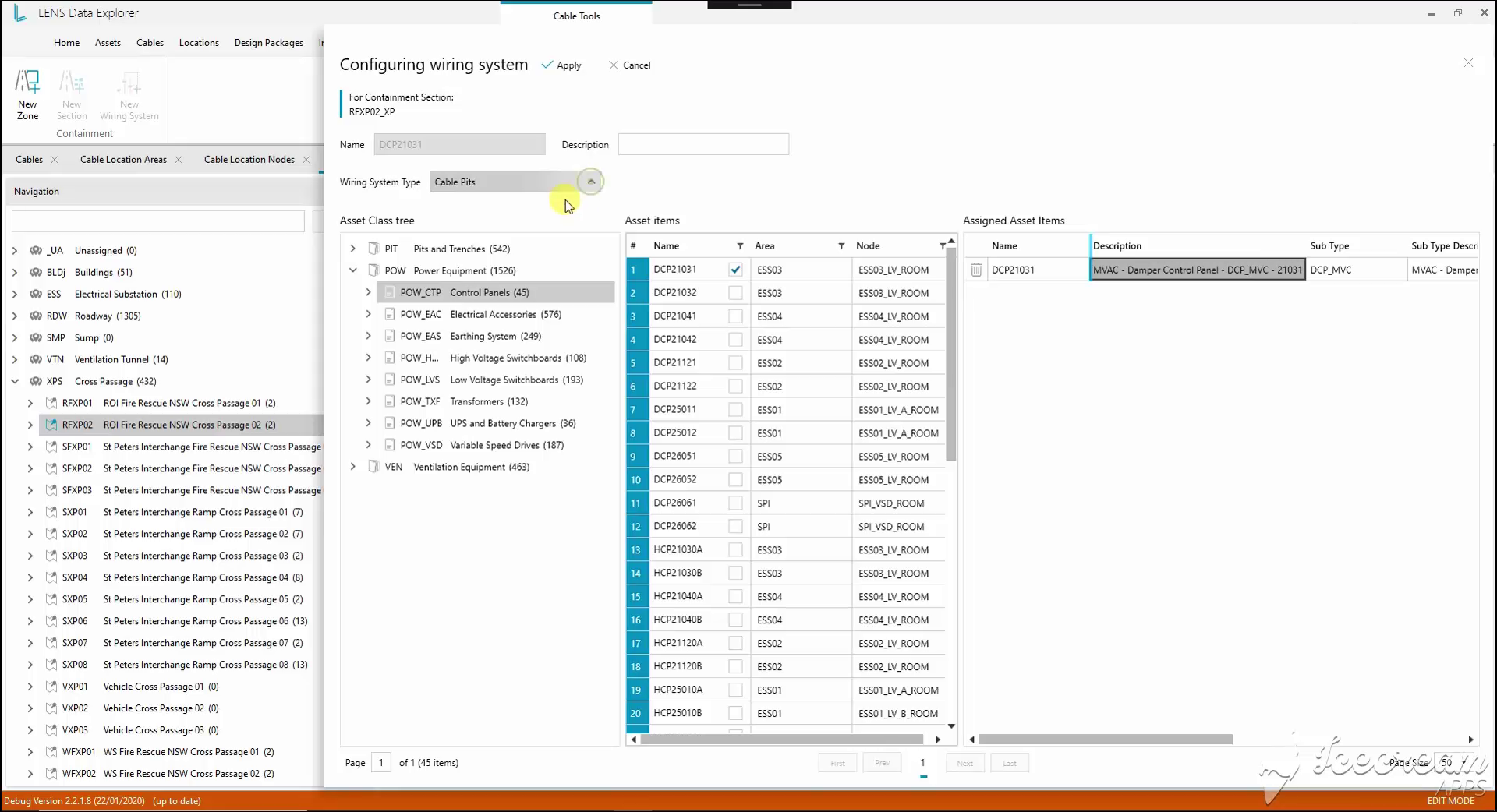
The chosen asset appears in the assignment list with its description and subtype. Its original position in the equipment tree remains visible, making the selection easier to verify before applying it.
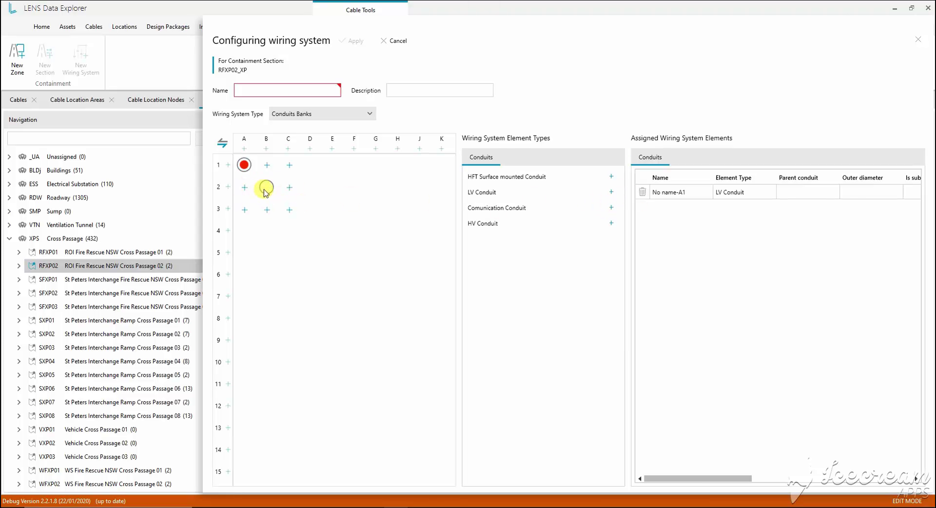
A coordinate grid places conduit elements within a bank. The adjacent catalogue offers low-voltage, high-voltage and communication types; the assigned list holds each element’s diameter and parent relationship.
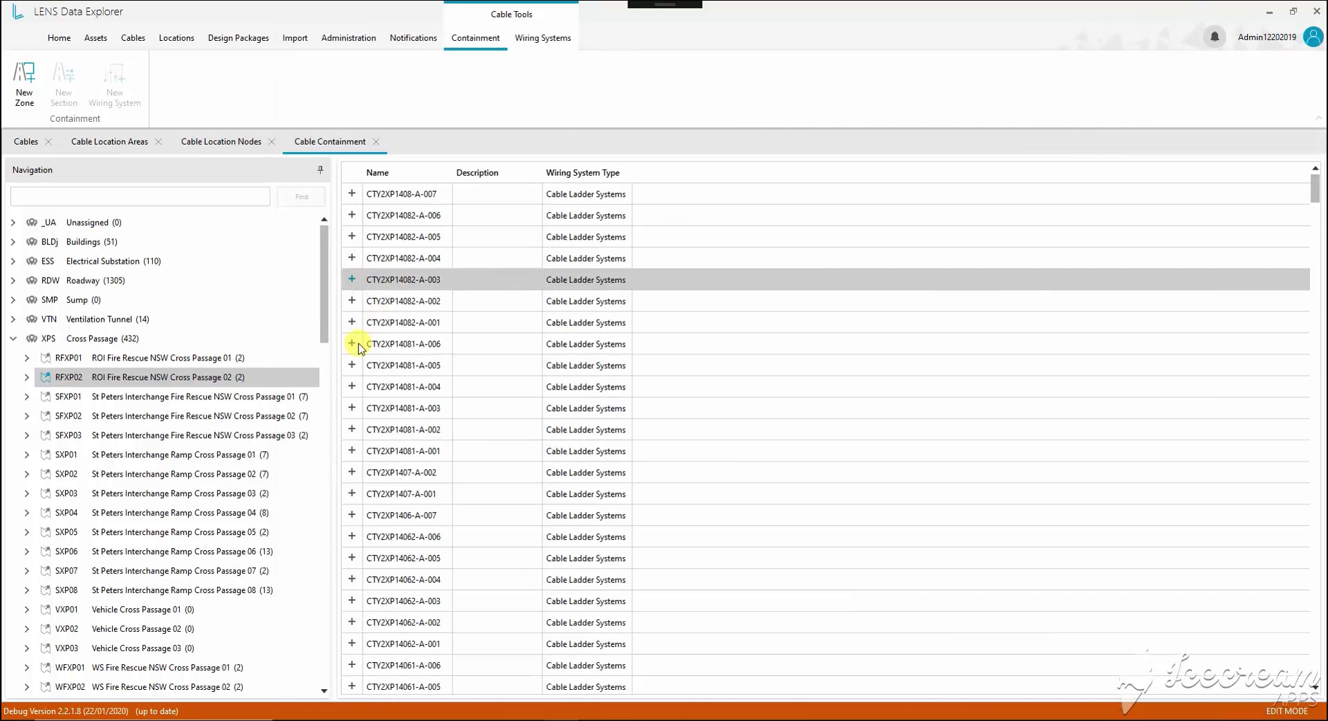
The location tree leads to a list of named wiring systems. Each row can be expanded to inspect its components, keeping the wider location visible while moving into the construction details.
Cable containment needs named zones and sections linked to physical locations, with the installed component specification available for review.
The location tree leads into expandable systems; creation forms retain the parent zone and location, and section rows expose material, diameter and space-factor properties.
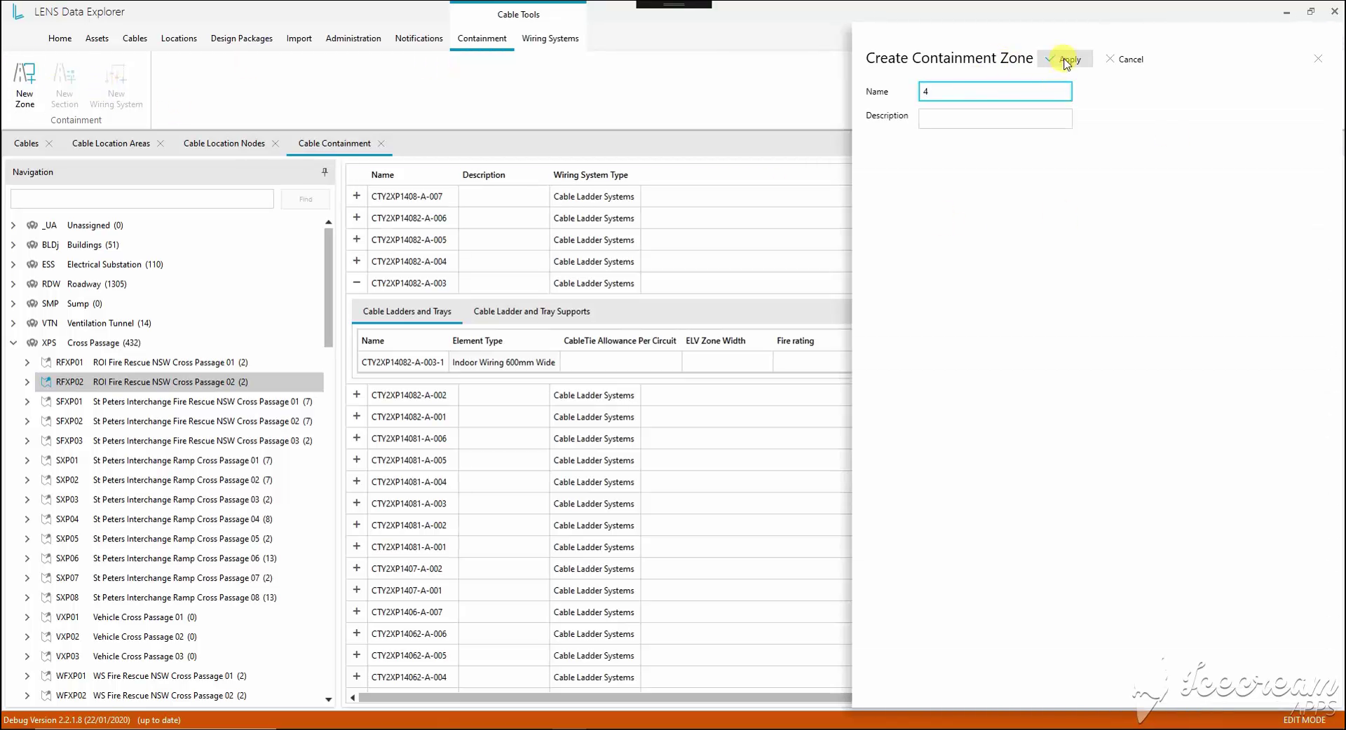
A compact side panel captures the new zone’s name and description. The containment register remains visible behind it, preserving the workspace context while the new zone is defined.
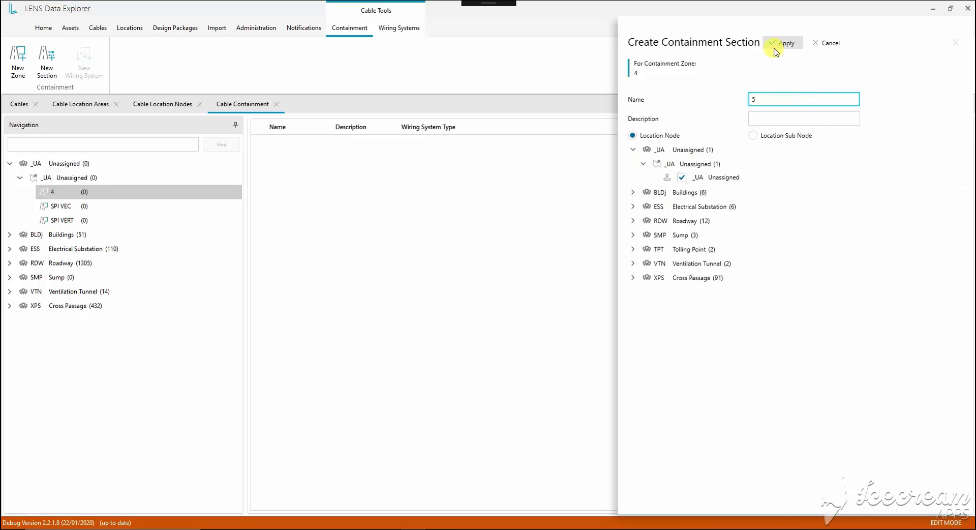
The section form shows its parent zone and a location selector. Engineers can choose a location node or subnode, linking the new containment section to the infrastructure hierarchy.
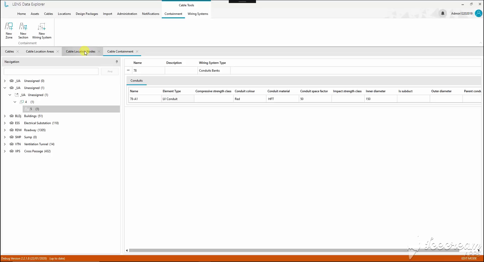
Opening a section exposes the conduits assigned to its wiring system. Material, colour, inner diameter and space factor are available in the component row for checking the selected specification.
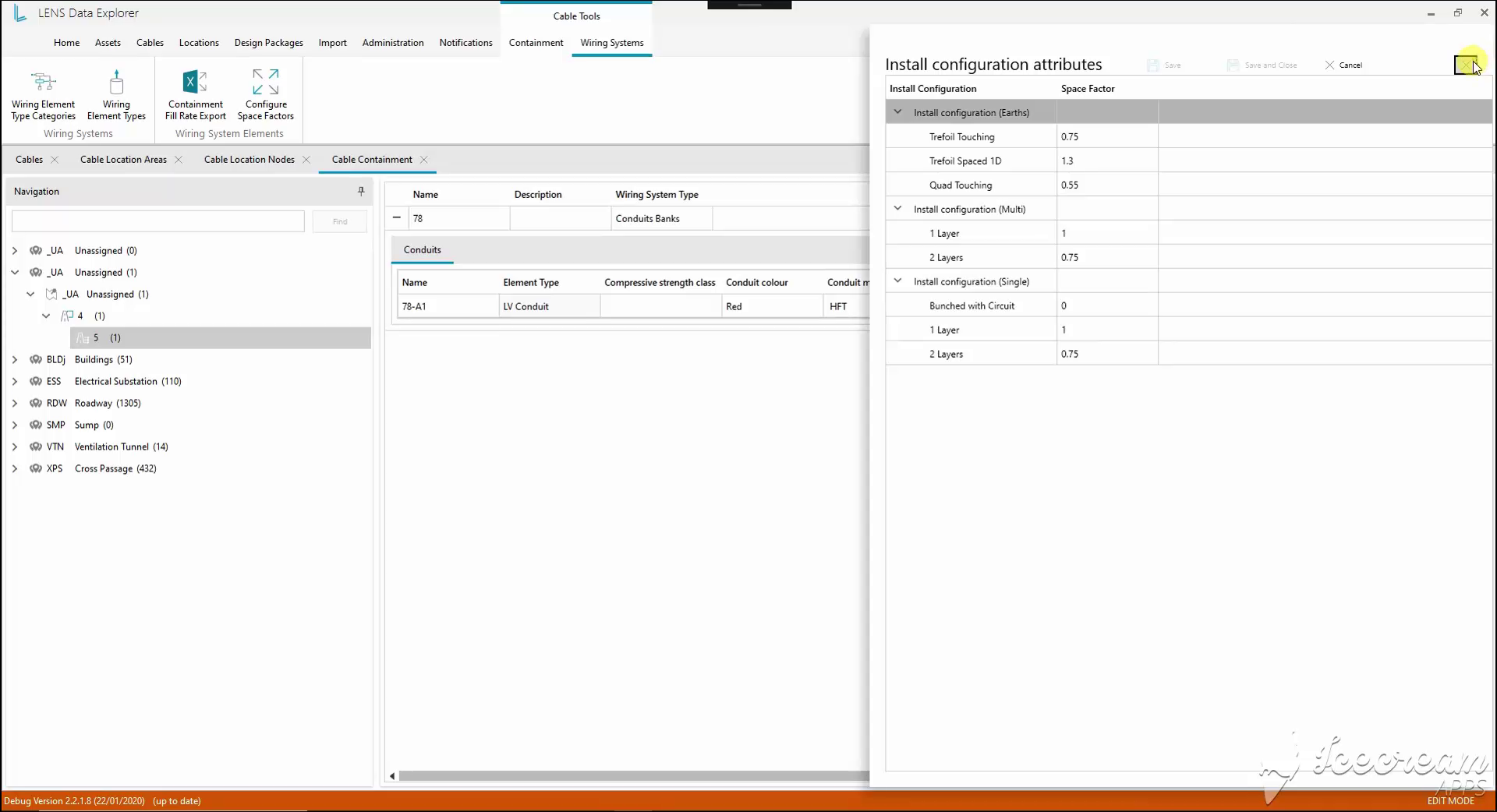
Installation arrangements are grouped for earth, multicore and single-core cables. Each arrangement has a space-factor value, keeping the assumptions for different layouts visible in one configuration table.
Reviewing containment fill requires explicit installation factors and component definitions, with each reported value linked to the corresponding element.
Configuration tables maintain installation arrangements and component attributes; the Excel fill report preserves the area, zone, section, system and element for each percentage.
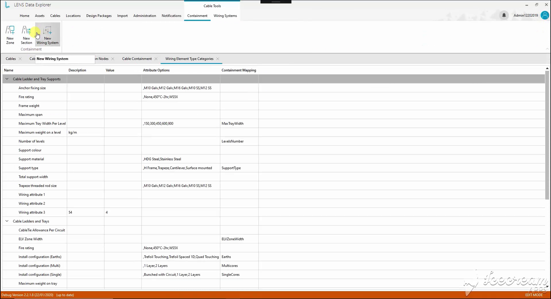
The component dictionary includes fastening sizes, support materials, fire ratings and installation options. Attribute choices and containment mappings specify how these properties are used across wiring-system elements.
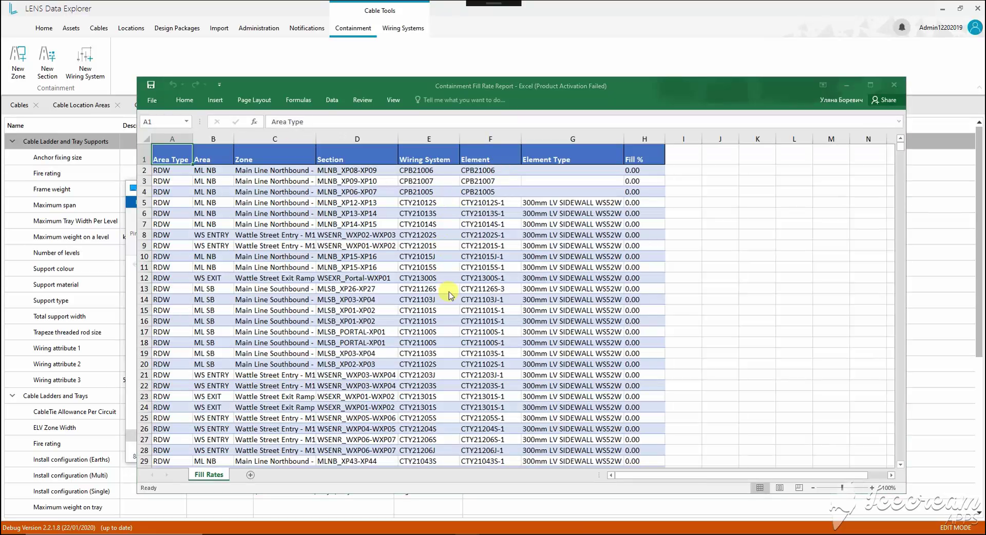
The Excel report links fill percentages to the area, zone, section, wiring system and element. Each reported value can be traced back to a specific part of the containment structure.
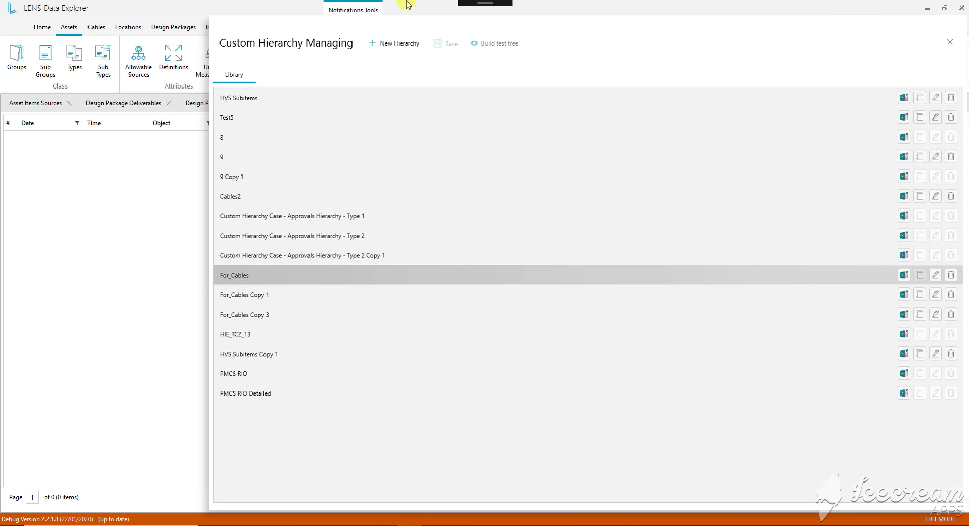
The hierarchy library holds named configurations for different engineering tasks. Copy, edit and export actions let the team reuse a structure or develop a separate version for another review.
Engineering teams need alternative ways to group the same equipment and a way to inspect classification rules before using a hierarchy.
The hierarchy library and builder define sources, levels and filters, preview the resulting tree with record counts and expose unassigned records for investigation.
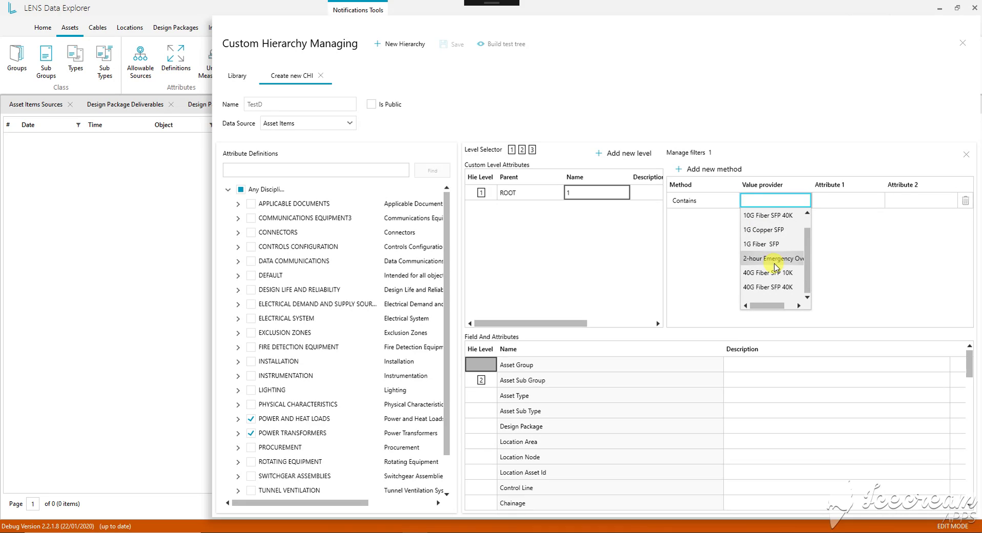
The builder combines a data source, hierarchy levels, asset fields and selected attributes. Per-level filter methods determine which records belong together, making the grouping rules explicit.
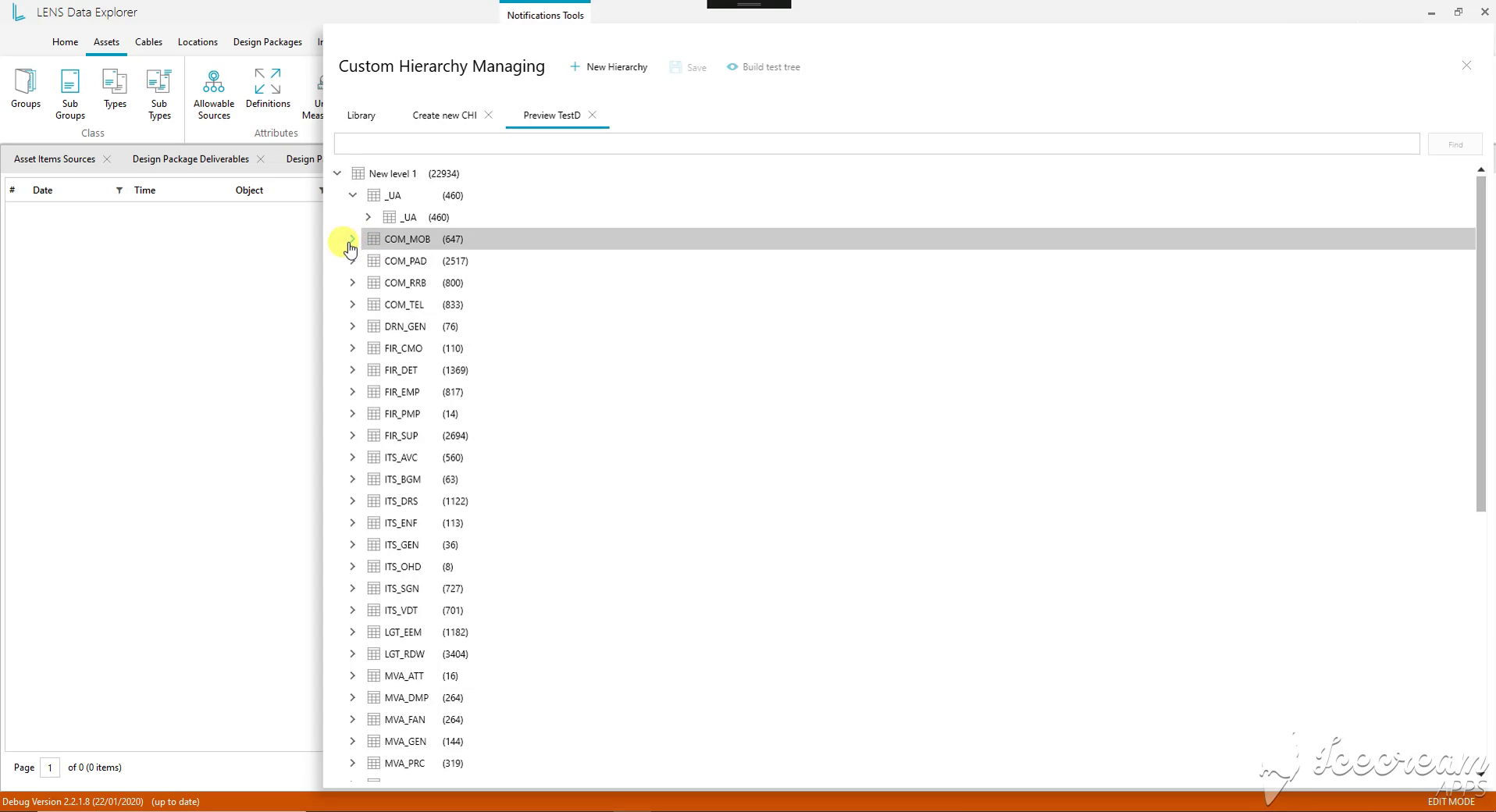
The test preview renders the configured hierarchy as expandable branches with record counts. Engineers can inspect where equipment is grouped before opening the hierarchy as a working view.
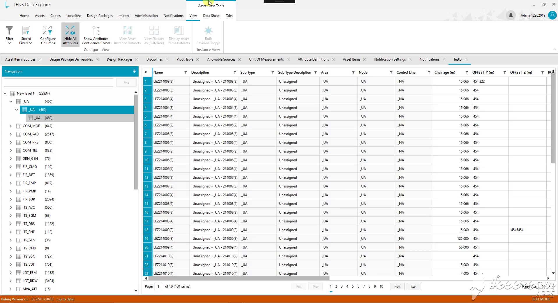
The Unassigned branch brings unresolved records into a working table. Identifiers, descriptions and positioning fields remain available, giving the engineer a concrete selection to investigate and complete.
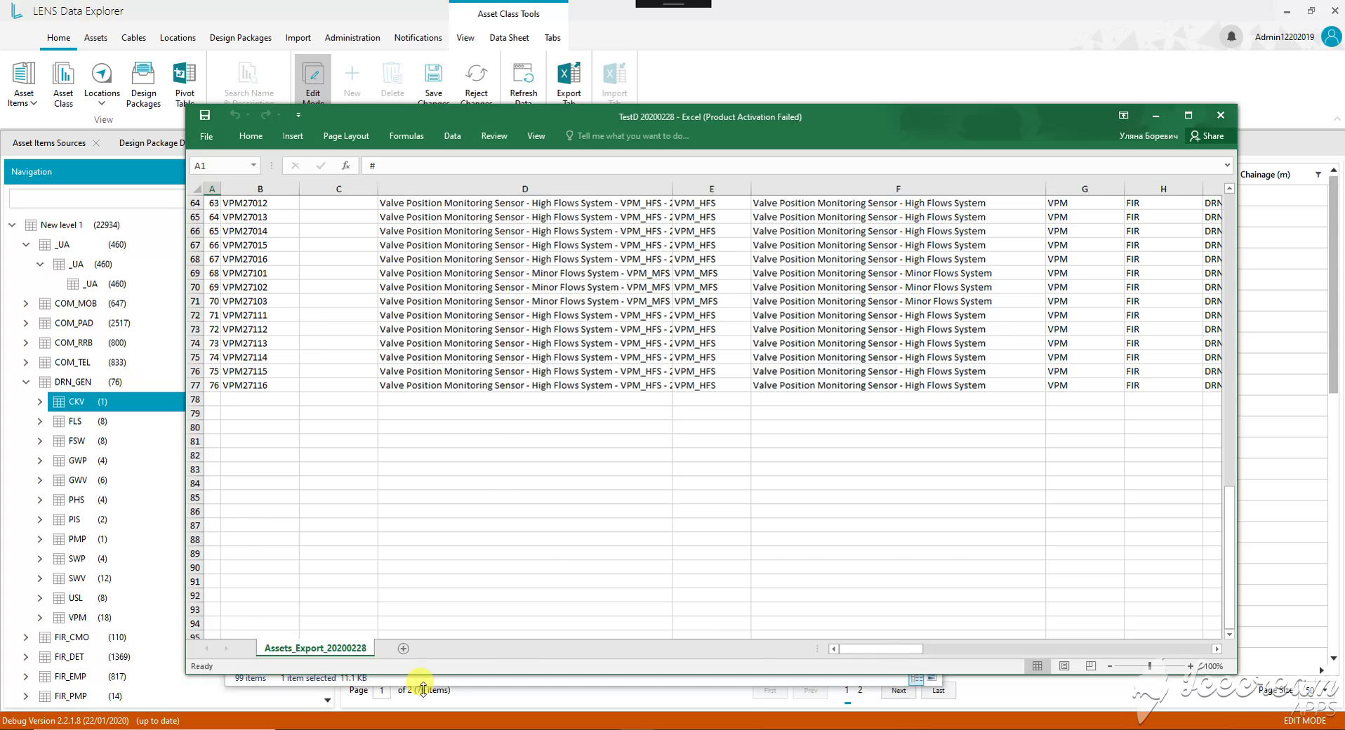
The exported worksheet preserves equipment identifiers, descriptions and classification fields. A team can review a selected family outside LENS while retaining references to the original engineering records.
Reviewers need to compare equipment within a system family and inspect a selected asset while retaining its classification and location context.
Hierarchy rows carry identifiers and level paths, an adjacent panel exposes asset properties, and Excel export keeps the selected equipment’s classification references.
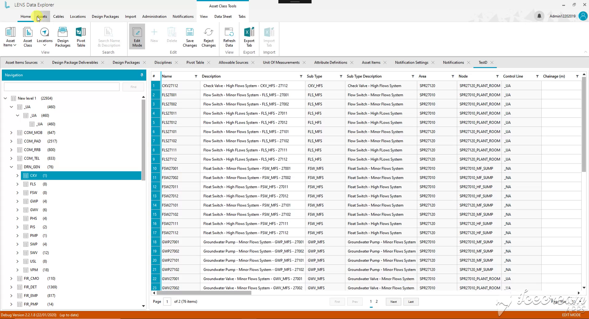
The drainage hierarchy brings valves, flow switches and pumps into the same register. Subtype descriptions and location references distinguish their roles and placement within the selected engineering family.
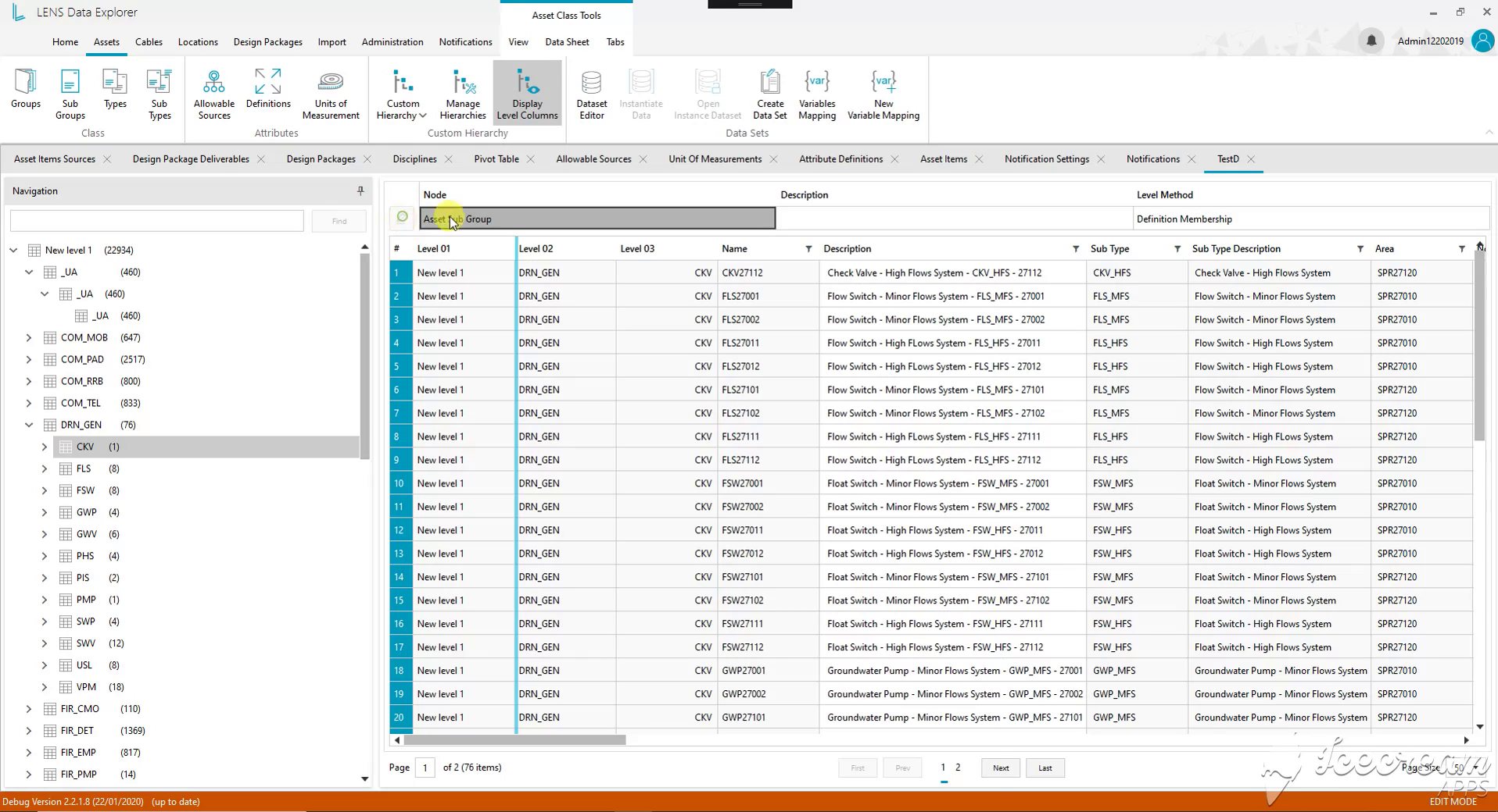
Level columns show the hierarchy path beside each asset identifier. The selected node also exposes its grouping method, helping the reviewer understand why a record appears in this part of the tree.
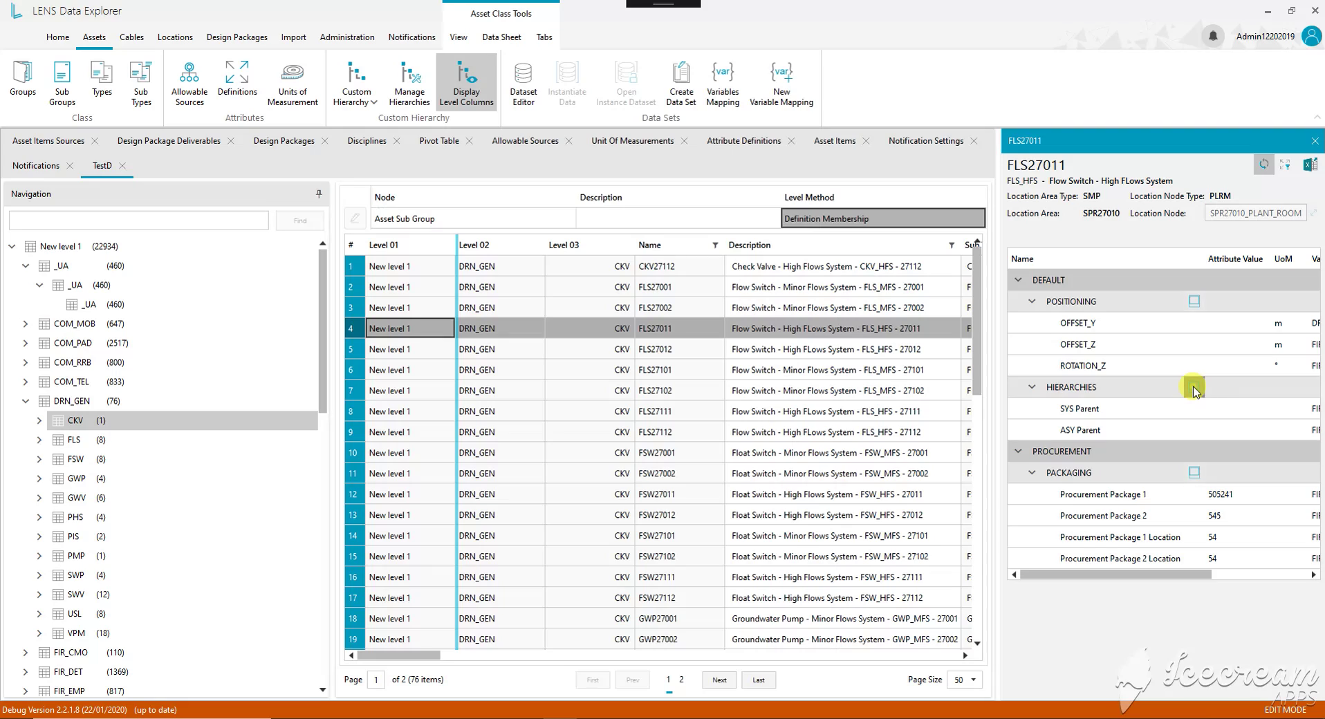
Selecting equipment opens its detail panel next to the hierarchy table. Positioning, parent relationships and procurement information can be inspected while the selected branch and neighbouring records remain visible.
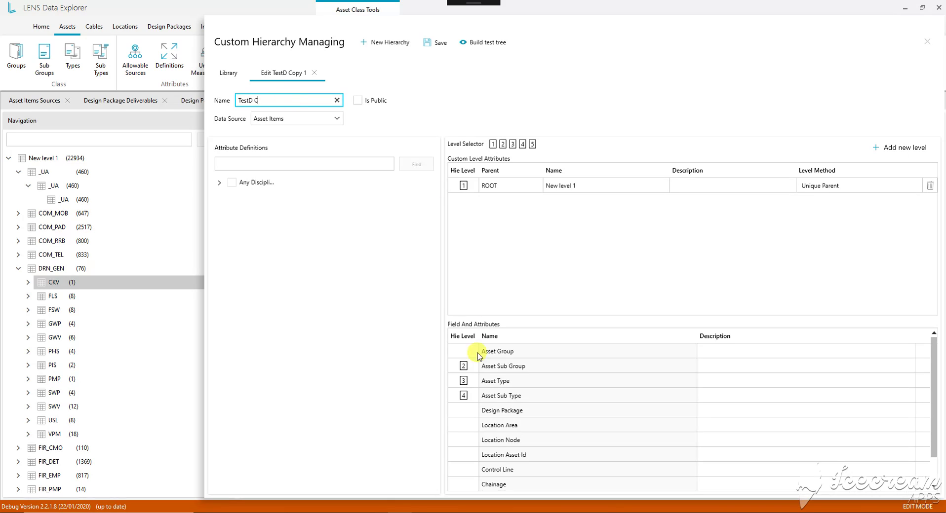
The editor maps asset groups, subgroups, types and subtypes to hierarchy levels. Naming, sharing and test-tree controls support reviewing a revised structure before saving it for further use.
Updating a hierarchy or importing a spreadsheet needs explicit choices about classification, the type of data and whether existing records are merged or replaced.
The editor maps classification fields to hierarchy levels, while import screens distinguish engineering entities, dataset modes, source files or folders, and Merge versus Replace behaviour.
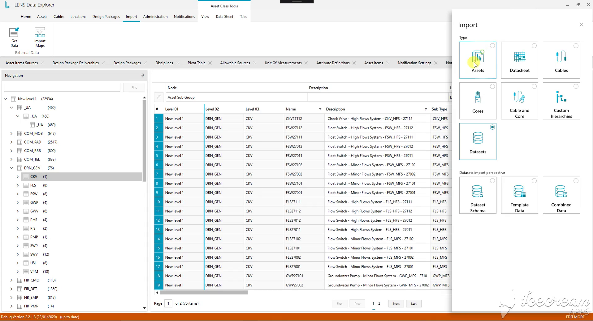
Import starts with the engineering entity: assets, cables, cores, hierarchies or datasets. Dataset imports further distinguish schema, template data and combined data, so the intended content is explicit before choosing a source.
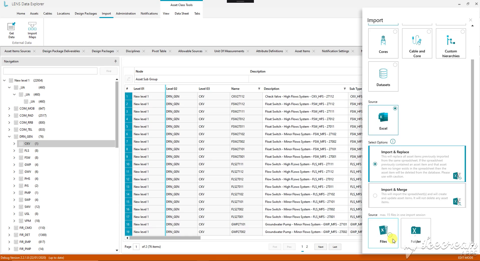
The Excel import distinguishes Merge from Replace. Merge creates and updates records; Replace can also remove records no longer present in the source spreadsheet. Files and folders are separate source choices.
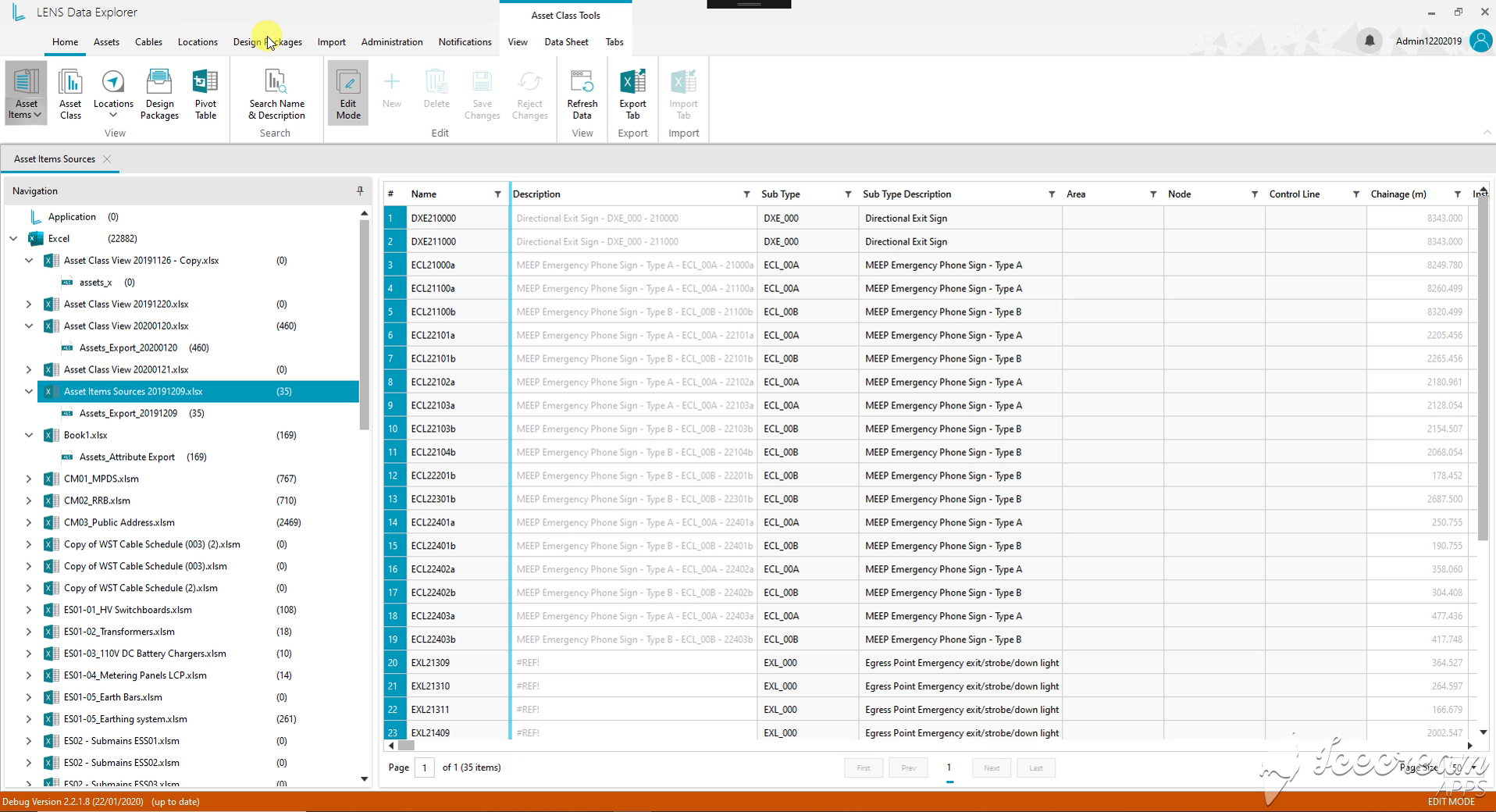
Source navigation lists imported Excel workbooks and their worksheets. Selecting a source exposes its equipment records, giving the engineer a starting point for checking where a particular set of data came from.
Engineers need to know where a record came from, how its dataset differs between revisions and which units give its values meaning.
Source navigation links records to workbook sheets, the pivot view compares revision snapshots, and the unit dictionary and detail panel retain measurement and attribute context.
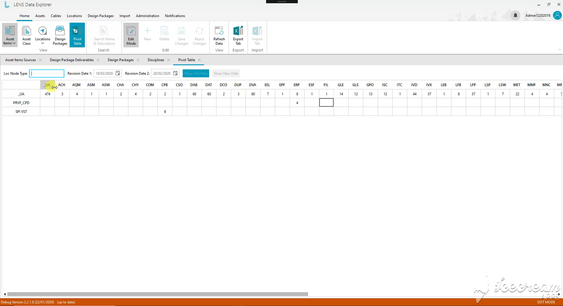
The pivot view crosses location nodes with equipment classes. Two revision dates and old/new data controls provide a basis for reviewing how the distribution of records differs between snapshots.
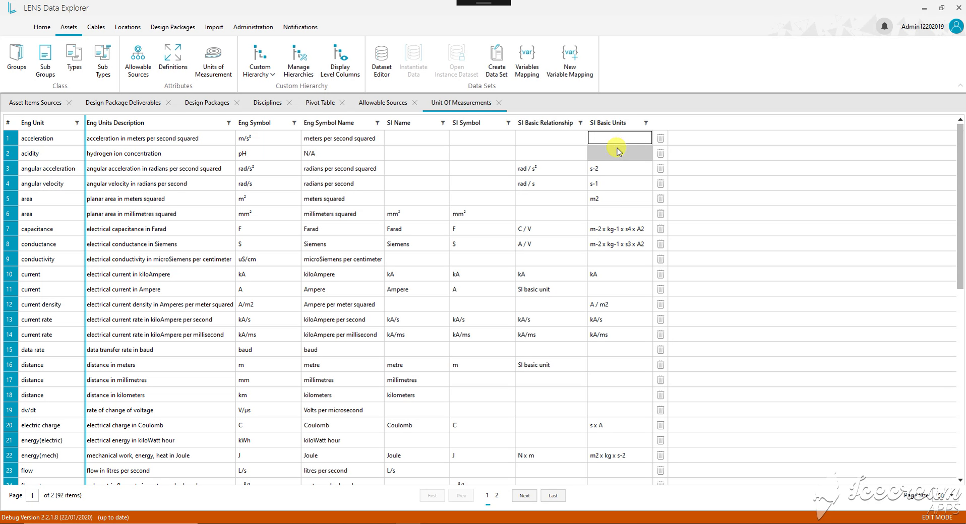
The unit dictionary records names, symbols, descriptions and relationships to SI units. It distinguishes values such as metres and millimetres, giving engineering attributes an explicit measurement context.
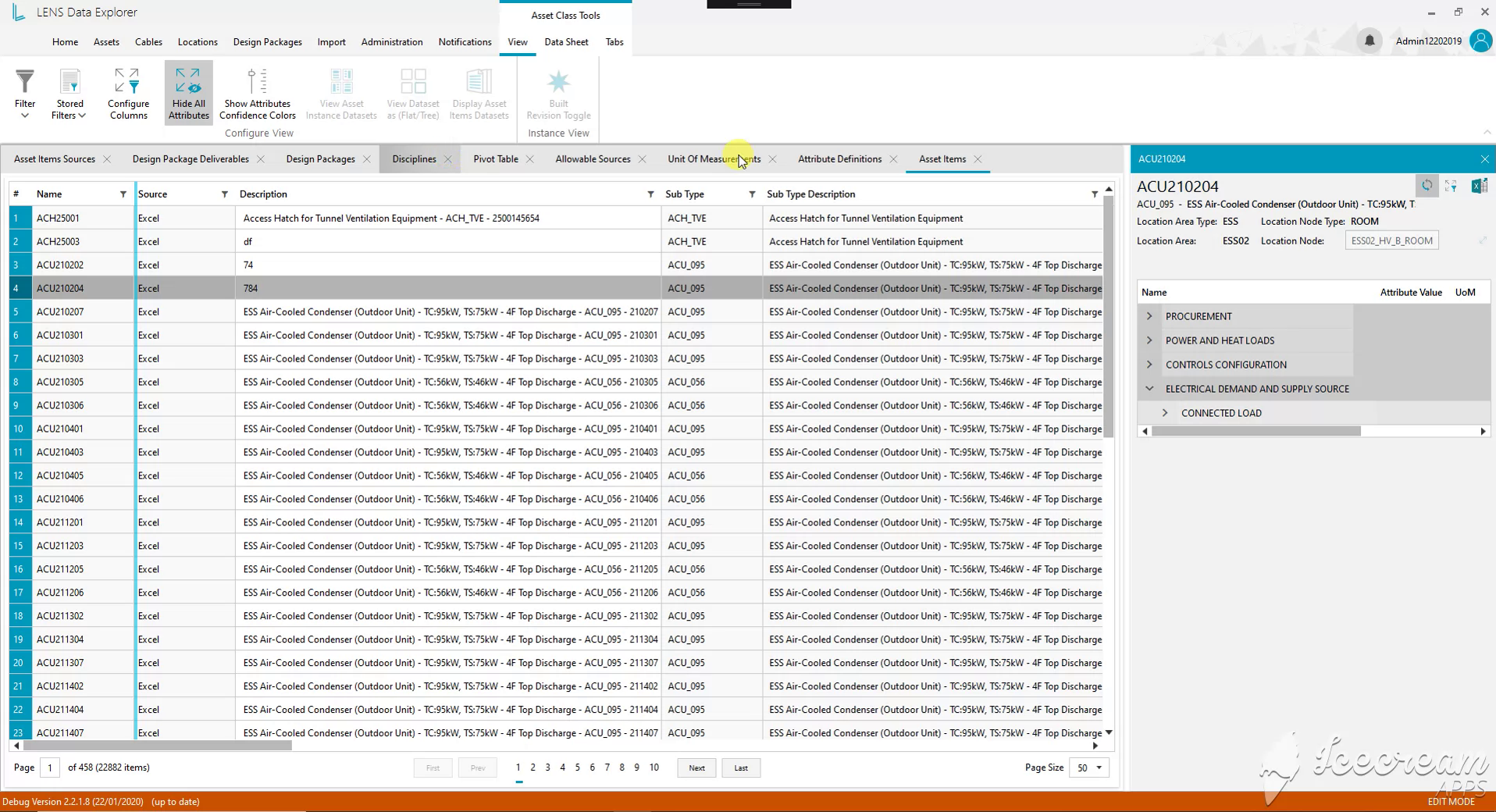
The asset list identifies the source and subtype of each record. The selected condenser opens its electrical, control and procurement attributes beside that list, bringing classification and technical details into one view.
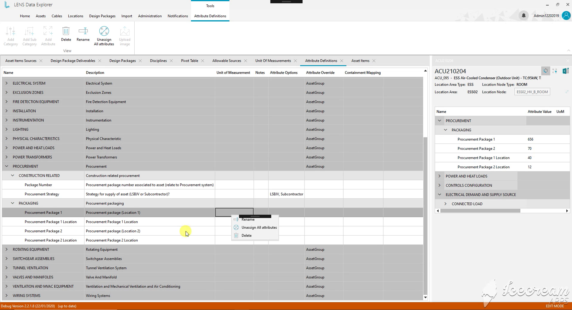
Attribute definitions are organised into categories and subcategories. Descriptions, units and allowed values sit beside the selected asset’s values, helping the team distinguish a field’s definition from its recorded content.
Teams need shared attribute definitions and reference material, then a focused way to review changes relevant to their equipment and responsibilities.
Attribute categories hold units, allowed values and image or PDF references; subscriptions select equipment and fields, and the notification register records the author, changed value and review status.
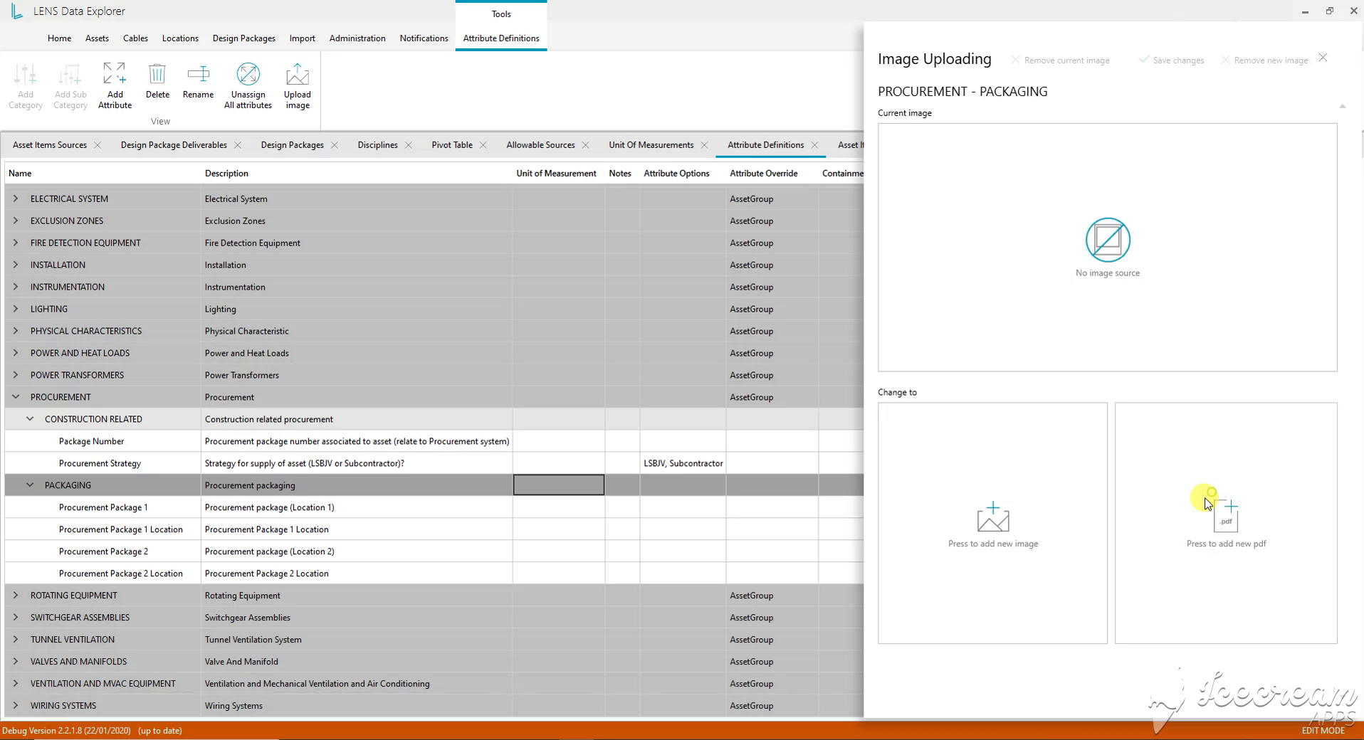
The attachment panel accepts an image or a PDF for the selected attribute category. It separates the current reference from its proposed replacement, with controls to save or remove the attachment.
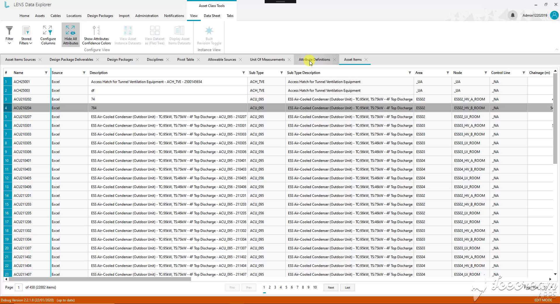
With the detail panel closed, the table shows source, subtype, area and location node together. Engineers can compare equipment records across the wider register and open a detailed card when needed.
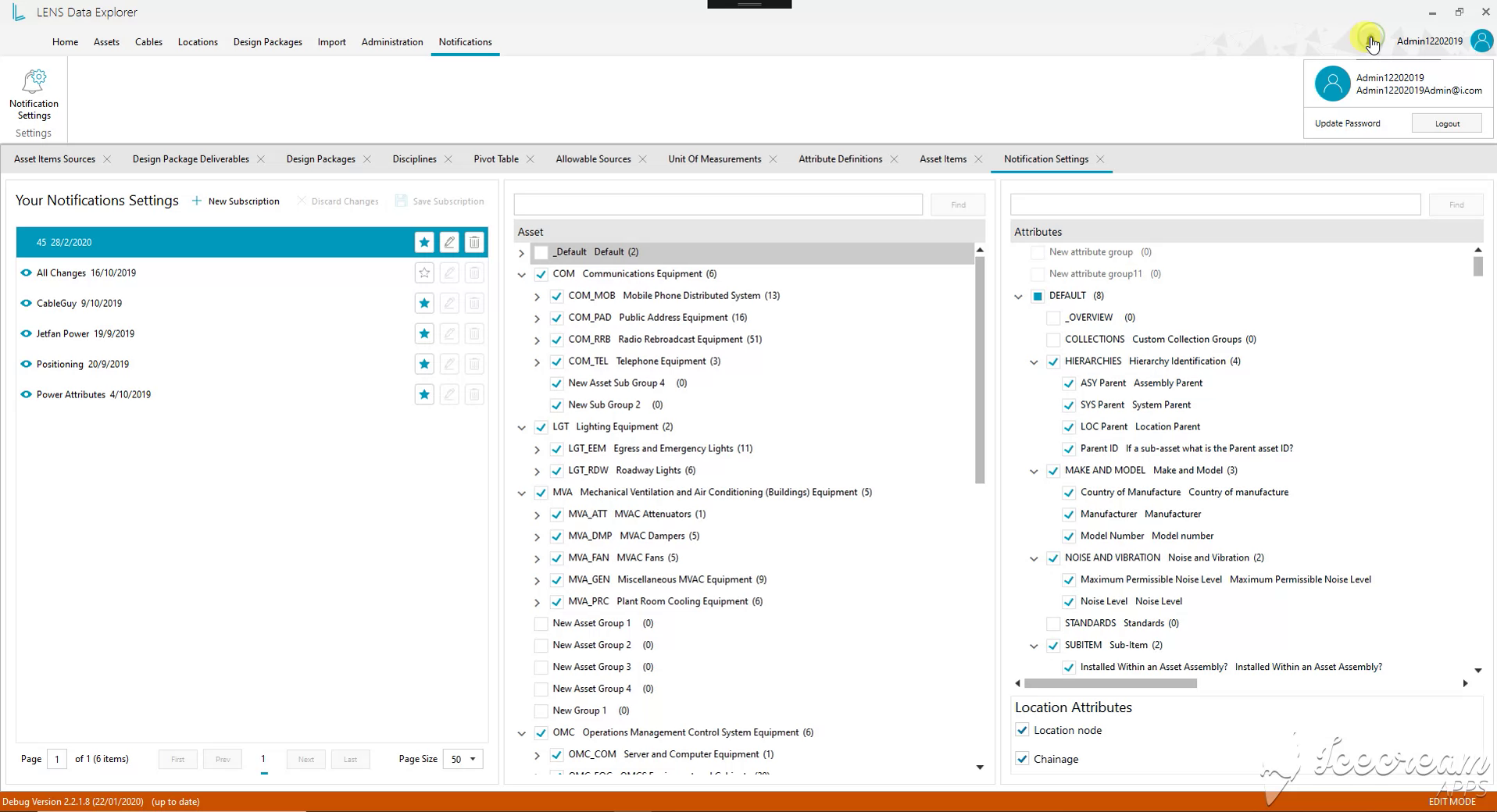
Notification subscriptions combine selected equipment families with specific attributes and location fields. Separate subscriptions can focus on different review responsibilities instead of treating every change as equally relevant.
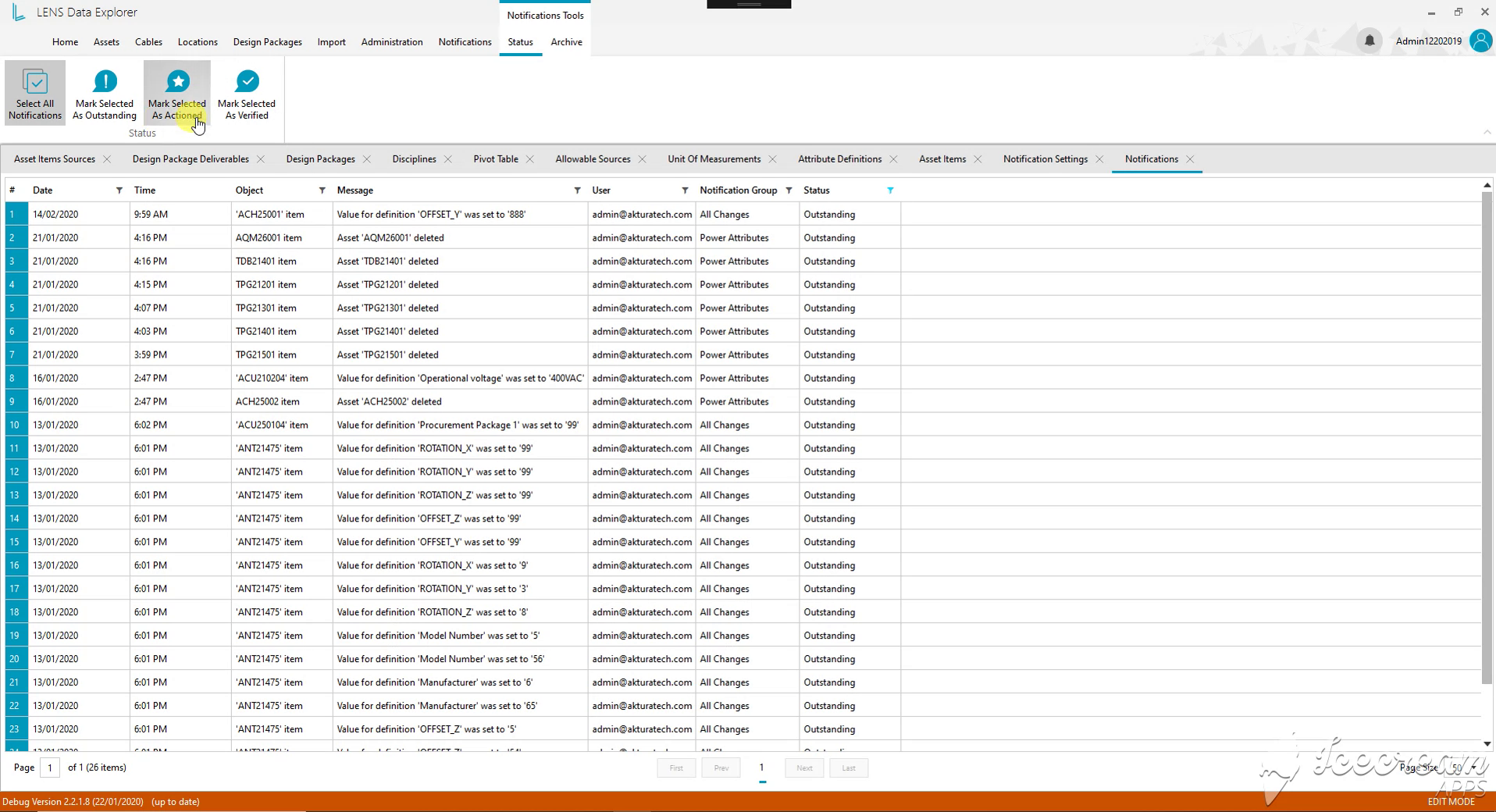
The notification register records the time, asset, changed value and user. Outstanding, Actioned and Verified statuses let the team distinguish a newly reported change from one that has been processed and checked.
A Windows engineering workspace supported by .NET services, SQL data and Azure infrastructure.
WPF and Telerik UI for WPF provide the Windows desktop interface.
C#, .NET Core and ASP.NET Core form the application stack, alongside Akka.NET, SignalR and MEF.
MSSQL Server and T-SQL provide relational data storage and queries. Entity Framework Core and Dapper support data access.
Azure Cloud is part of the project infrastructure supporting the engineering application.
Bring one asset family, its relationships and the information required at handover. We will map the data sources, revision history and reporting needs before defining the application scope.
Discuss your engineering workspace